Cantilever
SPM Basic Knowledge Q&A
Q3-1: Can you describe the cantilever?
Q3-2: What is the service life of cantilevers used in SPM systems?
Q3-3: What guidelines should be used for determining when to replace SPM cantilevers?
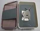
Q3-4: I am afraid of dropping the cantilever during installation. Is there a convenient tool available for installing them?
Q3-1: Can you describe the cantilever?
- This is a thin flexible strip about 100 µm to 200 µm long. The probe needle is located at the tip of the cantilever, but it is not visible to the naked eye.
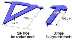
Examples of Cantilevers
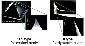
SEM Images of the Cantilever Tip
Examples of cantilevers are shown above (left), together with SEM photographs of the probe at the cantilever tip (right). The probe is integrated with the triangular or rectangular cantilever using a semiconductor manufacturing process, as shown above (left). Commercially marketed cantilevers are made of SiN (silicon nitride) or Si (silicon). Typical cantilevers are 200 µm long and 1 µm thick. The probe at the tip of the cantilever is typically 3 µm long, and has a point with a 20 nm radius of curvature. Various probe shapes are available, depending on the application. Some probes are coated with a magnetic substance, a metal layer, diamond-like carbon (DLC), or other materials.
Because the cantilever is extremely small, and projects from the approximately 1.5 mm x 2.5 mm base, tweezers are used to handle the base when replacing cantilevers.
Two types of contact mode cantilevers are available: a long type (200 µm) and short type (100 µm), but they differ only in spring constant, and they have identical probe shapes. The long cantilever offers easier optical axis adjustability, and applies a smaller force to the sample. The short cantilever offers superior sensitivity, due to higher leverage, and is often selected when a stiffer cantilever is required for systems vulnerable to static electricity.
There are many kinds of cantilevers available, such as those with various lengths and thicknesses, especially flexible cantilevers, extremely small cantilevers, and cantilevers made of carbon nanotubes (CNT), and new technologies are actively being developed. The Shimadzu SPM-9700 is designed to accommodate a wide variety of cantilever types, but beware that some cantilevers cannot be installed on all systems, and only specialized cantilevers can be used on some systems.
| Cantilevers for contact mode | SiN (34 chips per set) |
|---|---|
| Cantilevers for LFM | SiN (34 chips per set) |
| Cantilevers for dynamic mode (hard, standard) | Si (20 chips per set) |
| Cantilevers for dynamic mode (medium hard) | Si (24 chips per set) |
| Cantilevers for dynamic mode (soft) | Si (24 chips per set) |
| Cantilevers for MFM system | Si (20 chips per set) |
| Cantilever for current system | Si (20 chips per set) |
| Cantilevers for forced modulation system | Si (20 chips per set) |
| Cantilevers for Kelvin Force Microscope (KFM) system | Si (20 chips per set) |
| Cantilevers with carbon nanotube probe | Consult your Shimadzu representative for details. |
Q3-2: What is the service life of cantilevers used in SPM systems?
- Typically, cantilevers can obtain ten to thirty images at an image resolution equivalent to when they are new, but this varies considerably depending on the cantilever material and observation parameters, so it is difficult to generalize.
There is an extremely diverse set of factors that can affect the service life of cantilevers. Consequently, these factors cannot be summarized succinctly. Cantilevers can become unusable after acquiring a single image, or may remain usable for a week. Since the probe on the cantilever tip deteriorates with scanning, even if only slightly, it is commonly said that cantilevers are generally able to acquire about ten to thirty images at the same resolution as when new. After that, the probe point gradually becomes more rounded, and images lose their sharpness. Fig. 1 shows the difference between AFM images obtained using good and bad cantilevers.
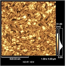
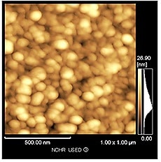
Fig. (a) below is an AFM image obtained using a cantilever before deterioration, whereas (b) is an image of the sample obtained using identical parameters and a cantilever after deterioration. The particles in this reference sample (vapor deposited niobium particles) should appear long and narrow, as shown in (a), but in (b) they appear rounder, blurry, and larger due to deterioration of the probe tip.
Difference Between AFM Images Obtained Using Good and Bad Cantilevers
(a) AFM Image with Cantilever
Before Deterioration
(b) AFM Image with Cantilever
After Deterioration
Cantilever deterioration depends on the material of the cantilever and its observational parameters (such as the scan range, scan speed, operating point values, and type of samples scanned). Cantilevers made of SiN generally last longer, whereas Si cantilevers don't last as long. Also, in some cases, when scanning highly contaminated samples, contaminants can be transferred to the probe, causing the image quality to suddenly worsen. On the other hand, the usability of cantilevers also varies significantly depending on the desired resolution (image quality). Consequently, cantilever deterioration can vary widely depending on many factors, and even the criteria for usability will vary. Therefore, it is impossible to specify a specific number of hours as their service life. In reality, a cantilever should be replaced when the operator finds an abnormal image, or senses that the resolution has changed during measurements of a familiar sample.
It may be economical to use older cantilevers for scanning large areas (low magnification) and new cantilevers for scanning small areas (high magnification), based on the resolution necessary, but few laboratories actually manage their cantilevers in this way.
Q3-3: What guidelines should be used for determining when to replace SPM cantilevers?
- Normally, the cantilever is replaced when the required resolution can no longer be achieved.
Cantilever deterioration is estimated from the images produced. Cantilever probe tip shape has a large effect on SPM image quality. Deteriorated probe tips can lead to blurry images (decreased resolution), which is caused directly by probe wear, probe damage, probe contamination, and other factors.
The most commonly occurring and difficult to judge phenomenon is probe wear. Wear progresses gradually during scanning, causing the probe tip to become more rounded. The progression of wear depends on the sample (surface bumpiness and hardness) and scanning parameters (scan range, scan speed, operating points, and feedback gain). Therefore, the cantilever replacement timing cannot be determined based on usage time alone. Normally, the cantilever is replaced when the required resolution can no longer be achieved.
In general, to prevent probe wear, reduce the scanning speed, reduce the operating point value, and specify an appropriate feedback gain. Wear can also be reduced by using a cantilever coated with diamond-like carbon (DLC), or a cantilever made using carbon nanotubes (CNT), but these are expensive and limited in variety.
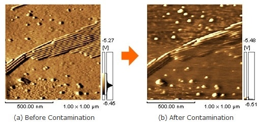
In contrast, it is easy to determine when to replace damaged or contaminated cantilevers, because the damage or contamination occurs suddenly. For example, the need for replacement can be determined based on the fact that the sample was just replaced, or that during scanning, a sudden change occurs in the images observed to that point. The figures below show an example of resolution suddenly decreasing due to probe contamination during scanning.
Example of Sudden Drop in Resolution Due to Probe Contamination During Scanning
The following are offered as guidelines for replacing cantilevers.
- The observed image of a standard sample looks different than normal.
Try observing a familiar sample frequently observed, or a standard sample included with the system. If the image appears different than normal, with the sample particles appearing larger than expected for example, the probe tip may have deteriorated. - The shape of the probe tip is evident in images (artifacts).
If the probe tip has a peculiar shape, then round particles can appear elliptical or elongated in a particular orientation for example, or triangular shapes may be observed, as shown in Fig. (a) below, or shapes may appear in sets of two or three, as shown in Fig. (b). Such artifacts as they are called typically maintain the same orientation even when the sample is rotated. This is because they are caused by the probe shape.
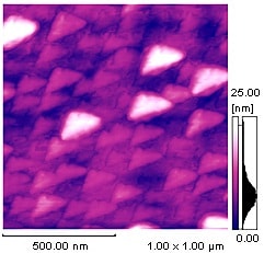
(a) Triangular Shapes Observed
in a Particular Orientation
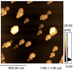
(b) Redundant Shapes Appear
Q3-4: I am afraid of dropping the cantilever during installation. Is there a convenient tool available for installing them?
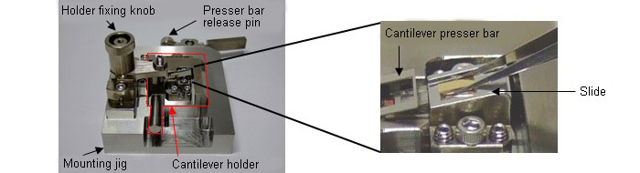
- Cantilevers can be installed reliably using an installation jig, which requires simply that you slide the cantilever into position.
- Mount the cantilever holder on the mounting jig and fix the holder using the holder fixing knob.
Then, press the presser bar release pin.
(The cantilever presser bar lifts up.)
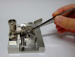
- Place the cantilever on the slide.
Pause a moment at this stage!
You can release and pinch the cantilever again in this step!
- Move the cantilever from the slide to the holder.
(The cantilever is set properly!)
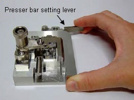
- Press the presser bar setting lever slowly.
The presser bar release pin will return and the cantilever will be fixed.
Applicable Cantilever Holders
Standard holders for AFM, holders for electric current, holders for minute electric current, and holders for KFM
- This jig cannot be used for cantilever holders for solution cells.
Product Configuration
1) Mounting jig main unit 1
2) Hexagon wrench for adjustment 4
3) Holding case 1
4) Instruction manual 1
* Patent pending