


Article
Making Best Use of Trinias Applications for Lower Extremity Interventional Procedures

- Department of Cardiology,
The Fraternity Memorial Hospital - Yasuhiro Takahashi
1. Introduction
The Fraternity Memorial Hospital was established on April 28, 1924, with donations received from the USA following the Great Kanto Earthquake that occurred on September 1, 1923. The earthquake caused more than 30,000 deaths, the greatest tragedy, at an army clothing depot close to the current site of our hospital (remains of the Yasuda residence, in Sumidaku). Our hospital is a general hospital currently with 373 beds, and 5 full-time doctors providing medical care in the Department of Cardiology. The hospital is focused on emergency cardiovascular diseases, with the Department of Cardiology receiving 787 cases brought by ambulance in 2015, and 104 cases of acute myocardial infarction. The hospital is also actively involved in the medical care of peripheral arterial disease (PAD), and is seeing an increasing number of affected patients in recent years. The Fraternity Memorial Hospital performs catheterbased examinations and procedure in two angiography rooms. Both rooms contain angiography systems from Shimadzu, with the first angiography room containing a BRANSIST safire system (9-inch single plane) and the second room containing a Trinias system (12-inch single plane) (Fig. 1). Although we were satisfied with the catheter-based procedures performed using the BRANSIST safire system, the Trinias system installed in March 2014 now plays a very important role in providing procedure of even higher quality due to its excellent image quality and wealth of applications. This article describes some of the functions of Trinias while presenting realworld cases where Trinias was used to administer peripheral lower extremity interventional procedure.
2. Main Trinias Applications Effective for Peripheral Interventional Procedure
- (1) SCORE RSM
- (2) Rotational angiography (SCORE RSM mode)
- (3) Peak hold function
- (4) MAP function/Trace MAP function
- (5) Sketch function
- (6) Blank MAP
(1) SCORE RSM (Fig. 2)
Bones and blood vessels often overlap in the arteries of the lower extremities, and using conventional digital angiography (DA) it was particularly difficult for us to display blood vessels below the knees.
Furthermore, while digital subtraction angiography (DSA) is excellent at displaying blood vessels since it removes the effects of bones, DSA also came with many shortcomings. These included a need for multiple exposures to acquire an entire lower extremity image since the bed must be fixed during imaging, and a serious susceptibility to target area movement during imaging that made it difficult to obtain good images from patients with serious lower extremity ischemia who often make involuntary movements. SCORE RSM allows bed movement during imaging since it produces a low-frequency mask image from images acquired after contrast medium injection, which is then subtracted from the original image in real time. This technique can create relatively well-enhanced images of blood vessels injected with contrast medium that are close to the quality obtainable with DSA.
- Fig.1
- Second angiography room with Trinias (12-inch FPD-equipped single plane system)
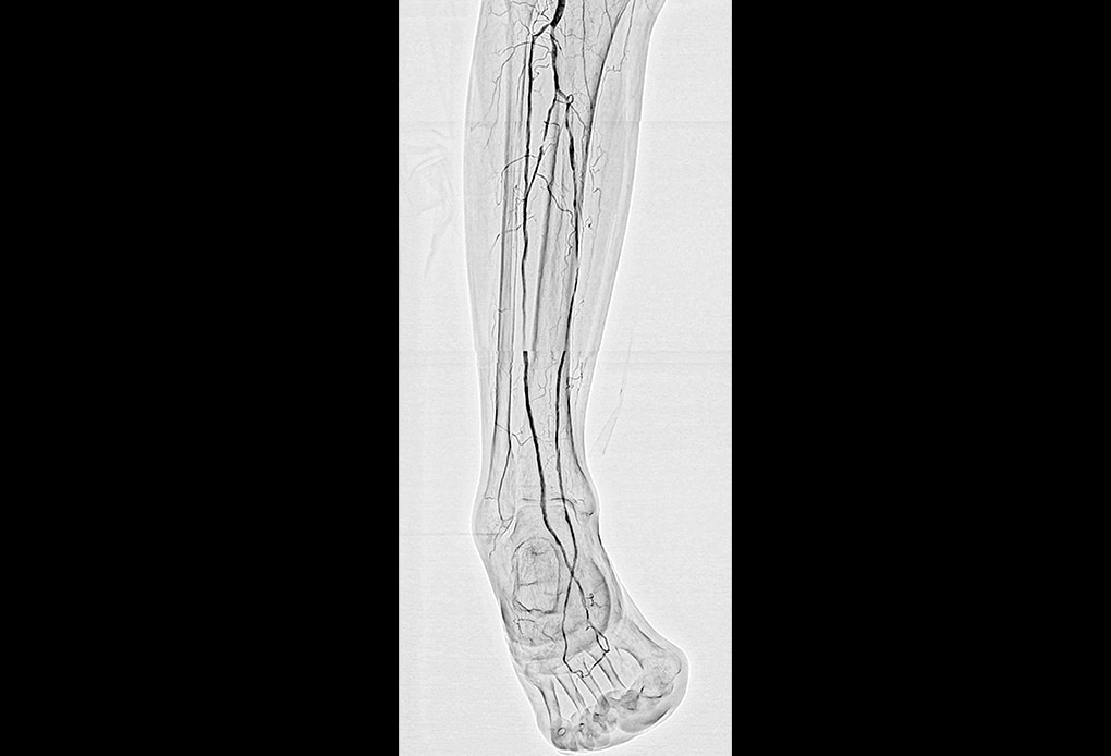
- Fig.2
- Image of arteries below the knee acquired with SCORE RSM Blood vessels are distinct with good contrast, even in the lower leg and foot where there are numerous bone shadows.
(2) Rotational Angiography (SCORE RSM Mode)(Fig. 3)
Although we previously performed rotational angiography using DA and DSA, rotational angiography by DA was not suited to the imaging of sites susceptible to bone shadowing, and rotational angiography by DSA was limited due to being susceptible to target movement.
For these reasons, rotational angiography was not used regularly for imaging cardiovascular areas.
However, since SCORE RSM is entirely unaffected by patient movement and removes the effects of bone shadowing where possible, it is an extremely useful imaging mode. SCORE RSM is particularly effective in displaying the plantar arch and collateral vessels below the knees, and allows us to obtain reference images and information on good working angles for passing guide wires through collateral vessels (Fig. 4).
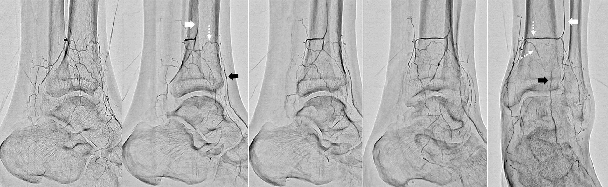
- Fig.3
- Rotational angiography using SCORE RSM from a micro catheter inserted into a side branch from the peroneal artery
Although bone shadows are visible, the collateral vessel is displayed clearly.
White arrow: Micro catheter inserted into peroneal artery
Black arrow: Distal portion of anterior tibial artery
White (dashed line) arrow: Collateral vessel from peroneal artery to anterior tibial artery
Reference
Image
Fluoroscopy
Image
- Fig.4
- Images acquired with SCORE RSM are used to select the working angle that will display the collateral vessel at its longest in the position of the guide wire. The guide wire is then passed through the collateral vessel under fluoroscopic guidance (right) while referring to the SCORE RSM image (left).
Arrow: Guide wire
(3) Peak Hold (Fig. 5)
The peak hold function processes individual frames to extract the parts of each frame that contain areas of peak contrast enhancement (darkest areas).
On a single frame, blood vessels can appear with varying levels of contrast due to the time it takes for contrast media to reach different parts of target vessels. The peak hold function only extracts the most concentrated results from contrast media for each part of the target vessels, and from this information compiles a single image. Use of carbon dioxide (CO2) as contrast media has recently increased in cases of kidney damage; however, the contrast of vessels with CO2 varies greatly from frame to frame compared with conventional iodinated contrast media. As a result, the peak hold function plays a useful role when CO2 is used as contrast media.
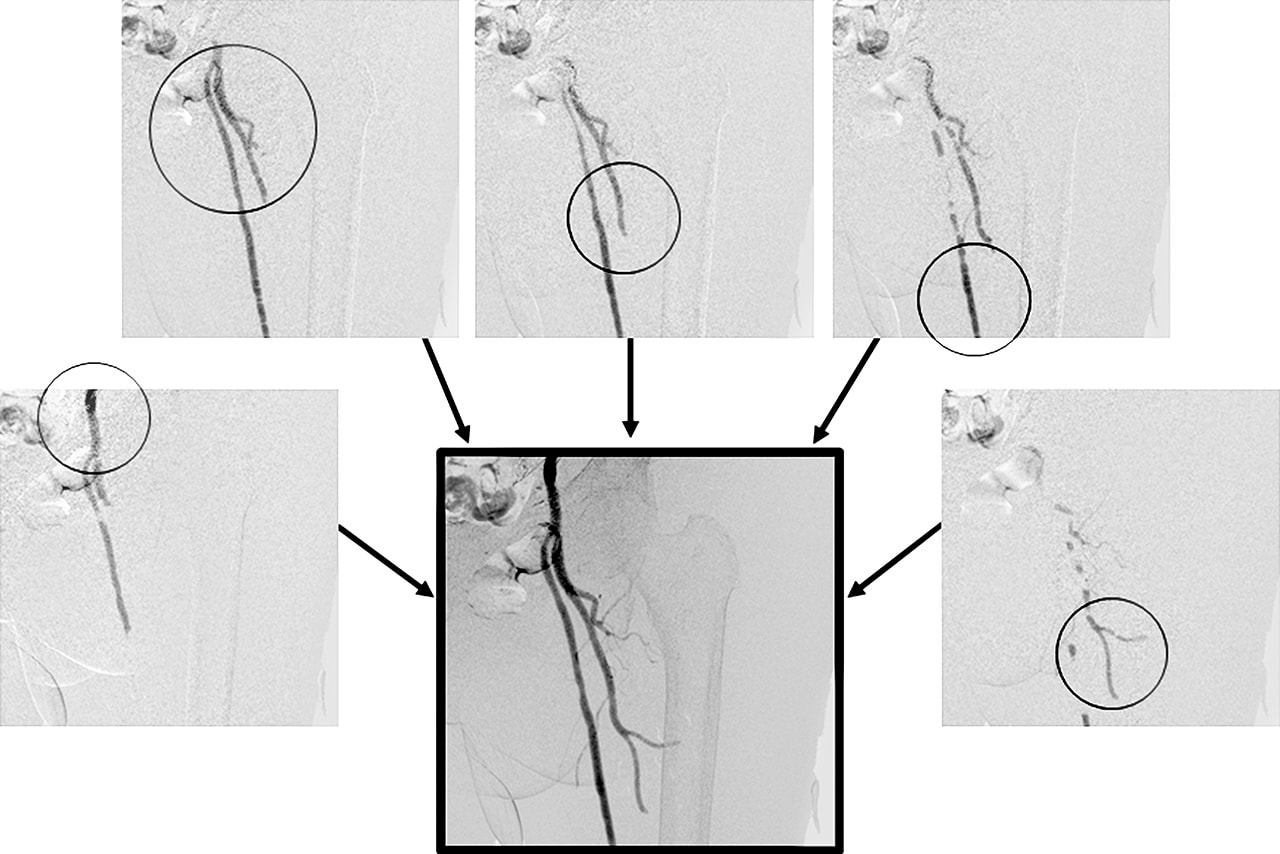
- Fig.5
- DSA image of femoral artery with CO2 contrast media
A large difference in contrast is apparent at each blood vessel on each frame. The peak hold function processes this information
to display a composite of the highest contrast at each vessel site (circled).
(4) MAP Function/Trace MAP Function
The MAP function extracts the blood vessels injected with contrast media from an acquired image, and superimposes this information onto fluoroscopy images. The MAP function is useful for aligning stents during placement, and for selecting branch vessels with a guide wire. The conventional MAP function shows blood vessels as white on the fluoroscopy image, which reduces the visibility of devices inside the blood vessel (Fig. 6). The conventional MAP function also had the shortcoming that when there was no sharp black/white contrast between the blood vessel and area outside the blood vessel, the conventional MAP function vessel image did not superimpose well onto the fluoroscopy image.
Trace MAP is able to automatically draw a white line around the outline of blood vessels and superimpose this outline onto fluoroscopy images. The radiological technologist can adjust the criteria for vessel outline detection while viewing the results of Trace MAP vessel outline processing. This allows Trace MAP vessel detection to be used when contrast media provides only mild contrast. Also, since it only shows outlines of blood vessels, guide wires that are passing inside the blood vessels remain relatively easy to observe (Fig. 7).
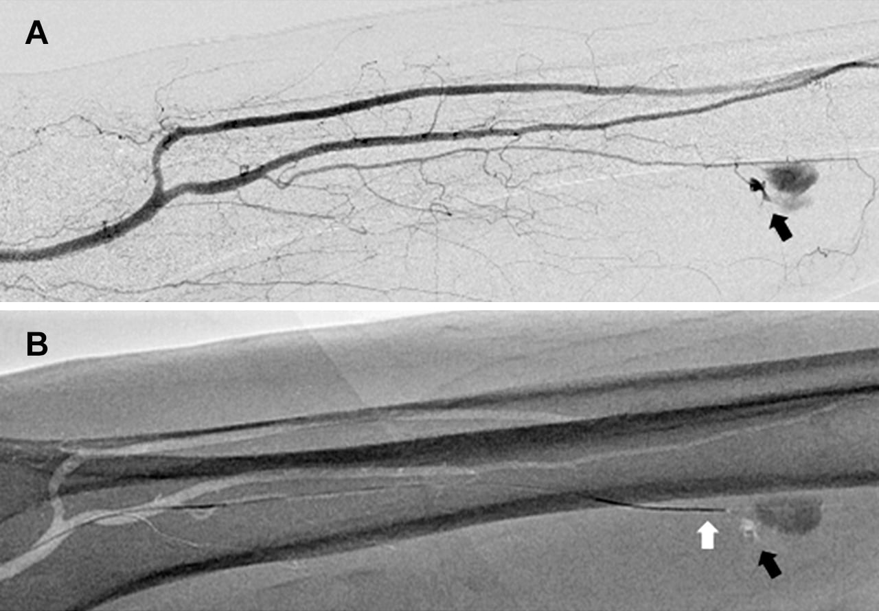
- Fig.6
- Sporadic lower leg hematoma
A: Conformation of bleed site by DSA (black arrow)
B: A MAP is created from the image obtained by DSA, and
a guide wire (white arrow) is inserted towards the bleed
site (black arrow).
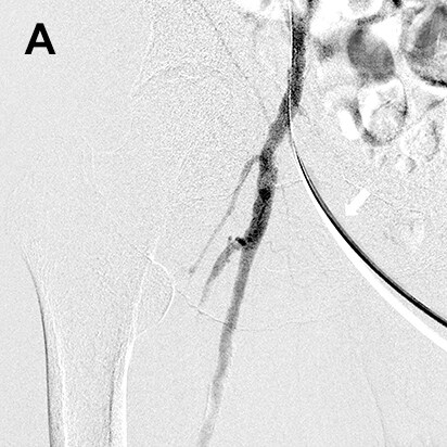
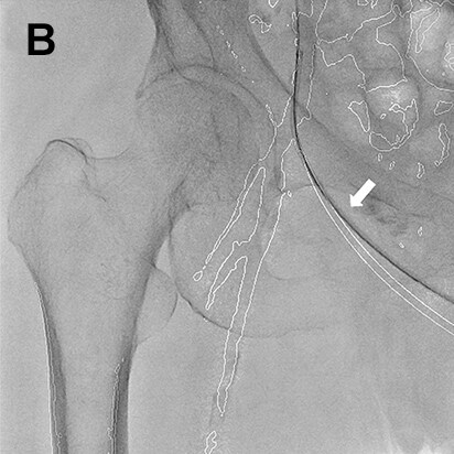
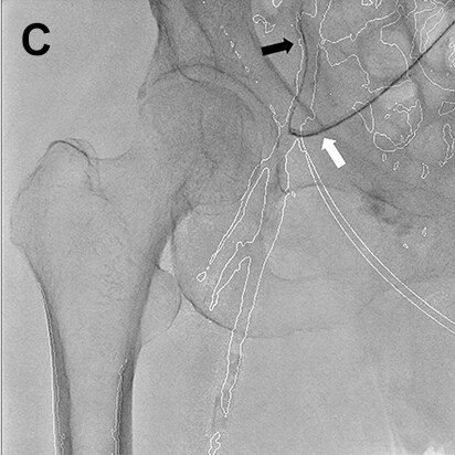
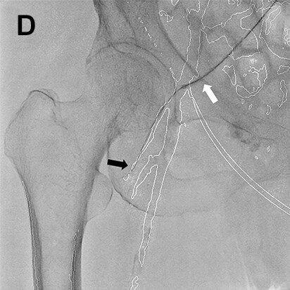
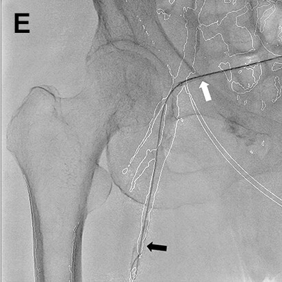
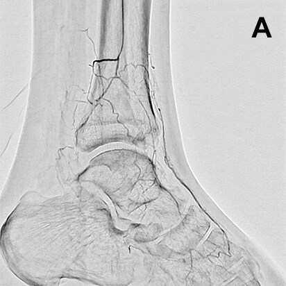
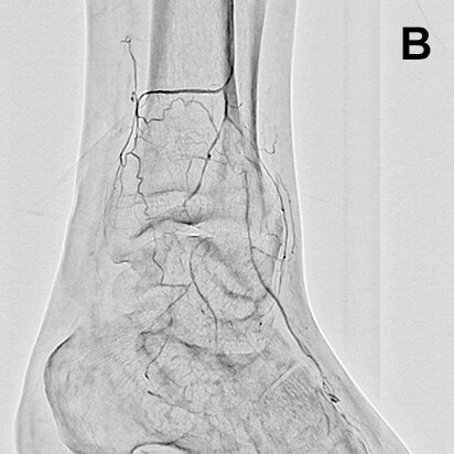
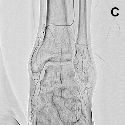
- Fig.7
- Procedure of a right below-knee lesion
Since no information on the iliac artery could be obtained by ultrasonography before procedure, the right common femoral artery was punctured perpendicularly, a guiding sheath was inserted into the iliac artery, and angiography was performed. After angiography, the guiding sheath needed to be reinserted distally in order to treat the below-knee lesion (switchback technique). In this case, the image acquired by DSA (A) was used to extract vessel outline using Trace MAP (B). The sheath was withdrawn carefully avoiding complete removal from the artery (C), and a guide wire was inserted in the deep femoral artery in a distal direction (D). Needing to steer the guide wire into the superficial femoral artery, Trace MAP was used in the same way to confirm insertion of the guide wire into the superficial femoral artery (E).
White arrow: Guiding sheath, Black arrow: Guide wire
(5) Sketch Function (Fig. 8)
The Sketch function allows the operator to overlay freely-drawn straight lines, curved lines, etc. onto fluoroscopy images. Lines that mark points such as important bifurcations and stent landing points determined by prior imaging can be drawn and used as landmarks during procedure. Although the purpose of using the Sketch function is close to those of the MAP (Trace MAP) function, at our hospital we use the Sketch function during stent placement and not MAP (Trace MAP). We use the Sketch function because landing a stent based on a landmark such as a straight line is simpler for stent placement. (The presence of anatomical structures in the fluoroscopy image such as those shown by MAP and Trace MAP is extra information that can distract the operator.)
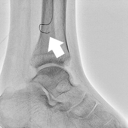
- Fig.8
- Accurate placement of a self-expanding stent in the common iliac artery just after a bifurcation
White arrow: Stent distal end marker Black arrow: Straight line displayed by Sketch function
(6) Blank MAP Function
This is the most recent software function added to Trinias systems. The Blank MAP function provides enhanced visualization of devices (radiopaque materials) introduced within the range of fluoroscopy on a subtracted fluoroscopy image. It makes possible to visualize devices without the influence of bone shadowing. Especially during neuro interventional procedure, visualizing the placement of an additional coil at the site of an existing coil can be difficult. The Blank MAP function subtracts an already-placed coil during placement of the additional coil, making the additional coil easily visible. Blank MAP is a useful technique for interventional procedure of the lower extremities, and is used at our hospital in the following three scenarios.
(6)-1 Blank MAP Use Case 1 —Introducing a Device (Fig. 9)
Devices newly inserted into the lower extremity area can be difficult to see on fluoroscopy, either because overlapping of bones and blood vessels is common in lower extremity areas or because the newly inserted device is hidden by another device. This results in a balloon or guide wire being inserted past the observation area because the operator could not identify the balloon end marker or the tip of the guide wire. This is a dangerous situation that can result in blood vessel perforation. Blank MAP is able to provide an enhanced image of a newly inserted device (guide wire, balloon, etc.) by subtracting existing devices shown by prior fluoroscopy or by subtracting bone shadows from the image. Effective use of the Blank MAP function can reduce complications during device insertion.
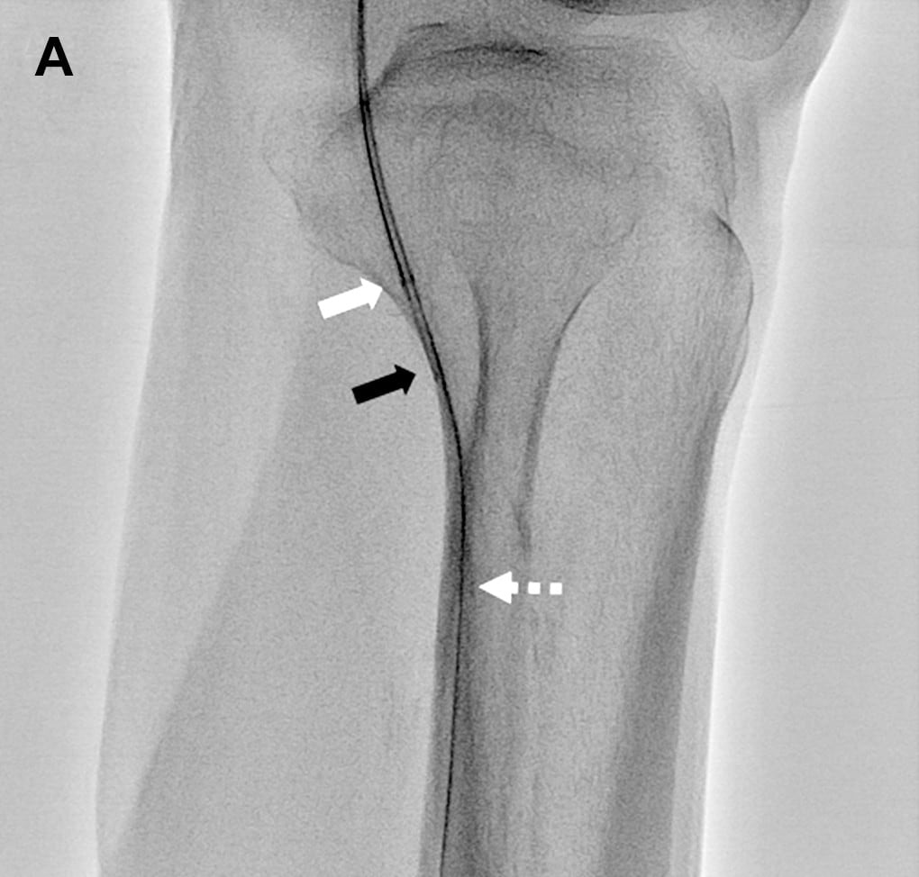
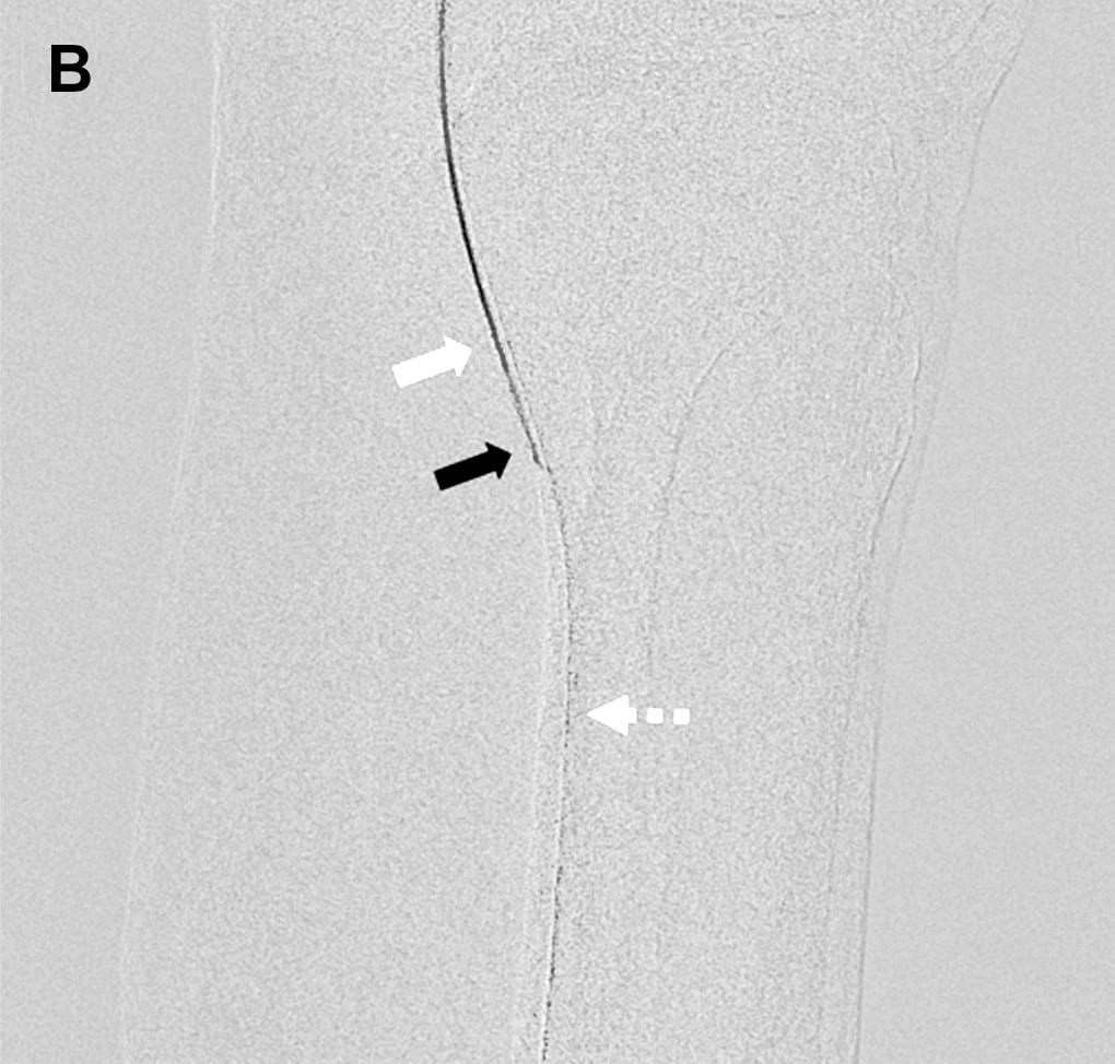
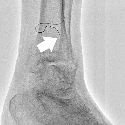
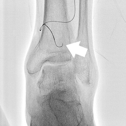
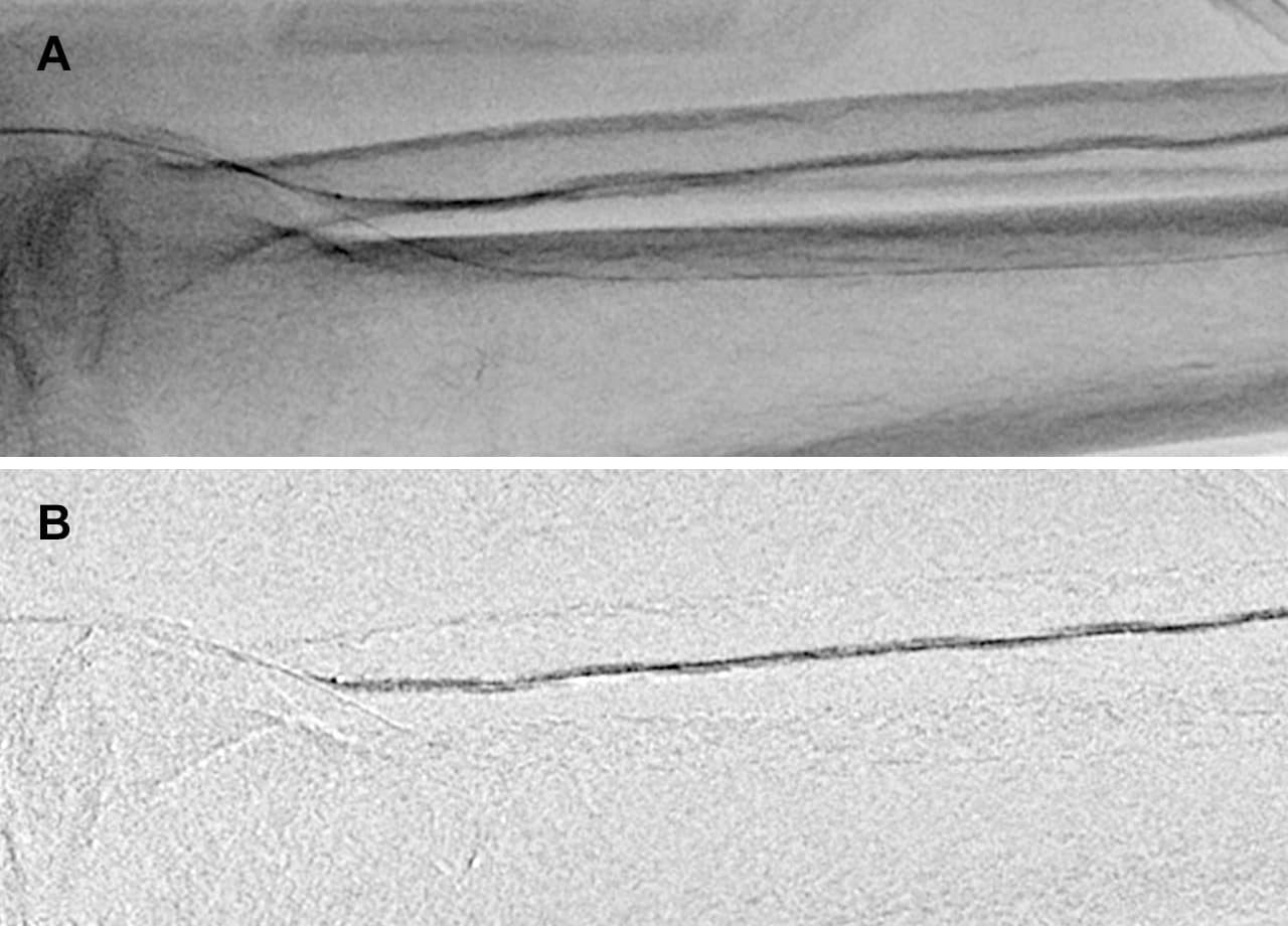
- Fig.9
- Comparison during guide wire insertion
(A: Normal fluoroscopy mode, B: Blank MAP mode)
A guide wire inserted by the antegrade approach inside a guiding sheath and micro catheter is more distinguishable during insertion when using Blank MAP mode (B) compared to a normal fluoroscopy mode (A).
White arrow: End of antegrade approach guide wire
Black arrow: End of micro catheter
White (dashed line) arrow: Retrograde approach guide wire
(6)-2 Blank MAP Use Case 2 —During Balloon Dilation (Fig. 10)
It can be difficult to confirm that balloon dilatation is adequate or not due to calcification or bone shadowing.
In these circumstances, Blank MAP can be used to confirm the degree of balloon dilation by subtracting the fluoroscopy image of the balloon before dilation.
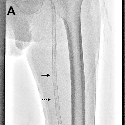
- Fig.10
- Balloon dilation for lower leg procedure
Using a normal fluoroscopy mode (A), the degree of balloon dilation is difficult to evaluate due to the balloon overlapping with bone margins. The Blank MAP mode (B) subtracts bone shadowing and shows that the balloon is fully dilated.
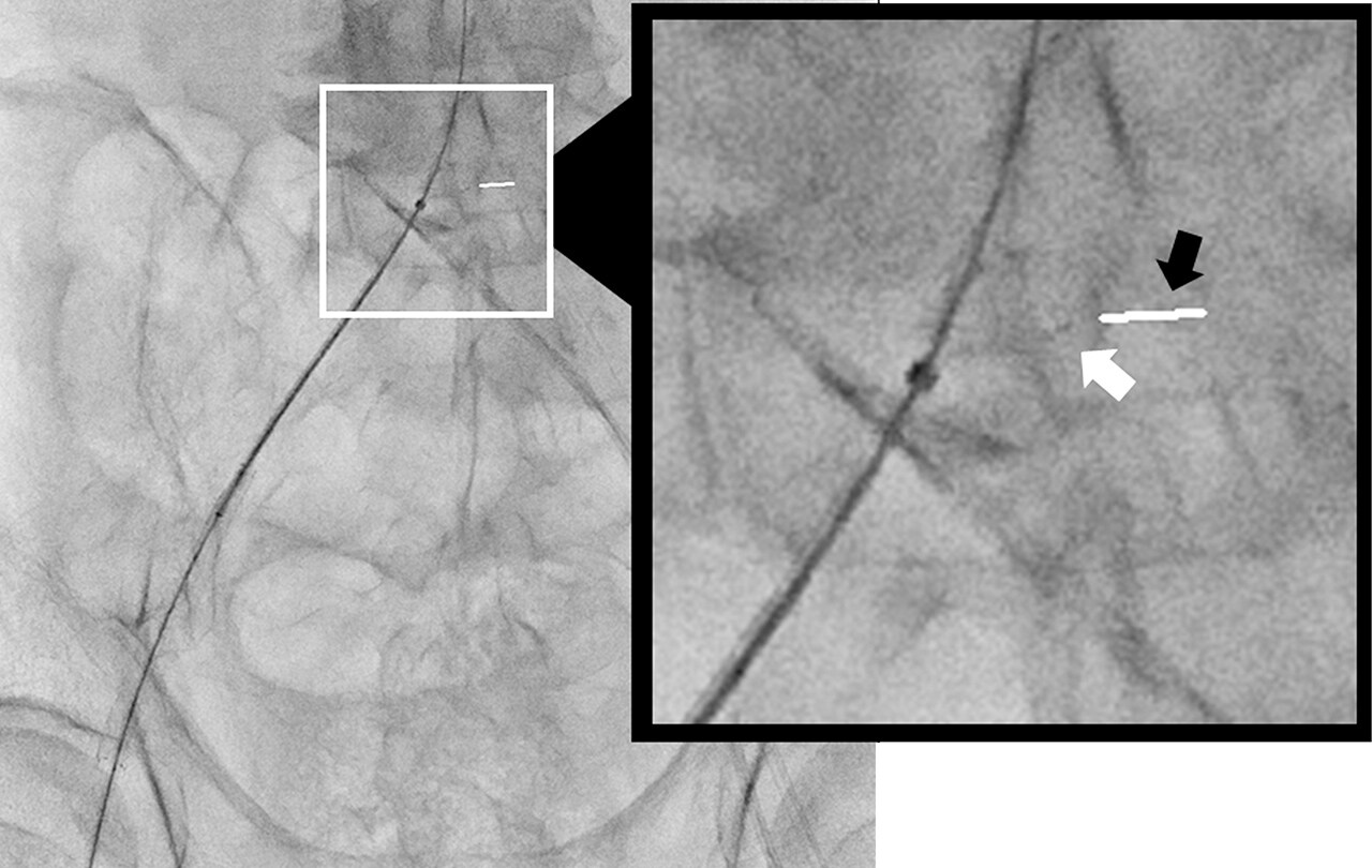
(6)-3 Blank MAP Use Case 2 —During Balloon Transfer (Fig. 11)
When a single ballooning is unable to cover the entire lesion, Blank MAP can be used during multiple additional ballooning. We switch to Blank MAP mode to perform balloon dilation after having delivered the balloon to the lesion. When the fluoroscopy switch is pressed again, and the balloon is moved proximally, the marker on the previous position is made negative by Blank MAP and so appears clearly in white on the image. To place the balloon just by the previous position, balloon dilation can be performed efficiently only with placing the distal marker over the proximal marker of previous position that is shown in white.
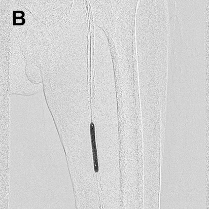
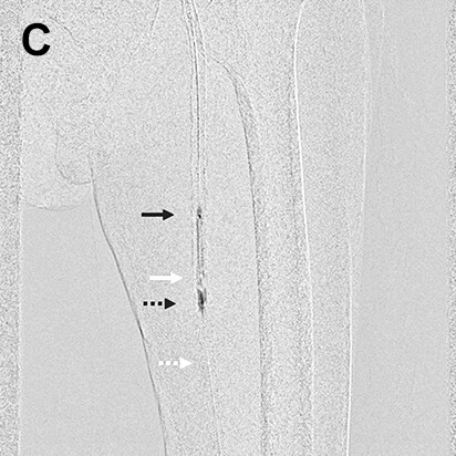
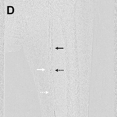
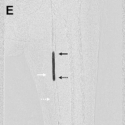
- Fig.11
- Balloon dilation at stenotic lesion in superficial femoral artery
The balloon was delivered to the area of the lesion (A), dilated at an initial position with Blank MAP mode turned ON (B), then deflated and moved to the proximal part of the lesion (C). The balloon was then dilated a second time with the distal marker on the moving balloon (black arrow with dashed line) overlapping the proximal lesion marker of the previous position of the balloon (white arrow) (D). The images show the proximal marker on the initial position of the balloon (white arrow) and distal marker on the balloon being moved (black arrow with dashed line) have moved out of alignment (E).
Summary
Dramatic progress has been made in lower extremity interventional procedures in recent years to the point that good results can be achieved from primary procedure. Another challenge to be overcome is the problem of procedural complications arising from human error. Significant progress has been made in angiography systems that not only provide clear images, but can also be used with a variety of applications to implement procedure. Trinias can be used with a large number of useful applications, from applications developed for lower extremity procedure, to applications developed to focus on other areas of the body. Optimal utilization of these applications by the operator is required not only to improve primary results, but also to reduce procedural complications.
2017.3