


Article
Optimal C-Arm Angle During DCA by Linking 3DCT and Angiography Systems

- Department of Cardiology,
Toyohashi Heart Center, Aichi, Japan - Maoto Habara
1. Introduction
Our hospital introduced a Trinias MiX system, produced by Shimadzu Corporation, (hereinafter, "Trinias") in May 2015 and now uses it as one of our main machines for PCI and EVT procedures. The Trinias also oers performance that is extremely useful for directional coronary atherectomy (DCA) procedures, so it has become our rst choice for such procedures. In this article, I will describe the angiography system performance required for DCA procedures and also use some clinical cases to illustrate the utility of the Trinias system.
2. Coronary Artery Perforation
The greatest concern when performing DCA procedures is complications from perforating a coronary artery. e risk of occurrence is about 0.3 %, which is not higher than other procedures, but it can result in sudden cardiac tamponade and sometimes even death. The causes include (1) errors in the longitudinal direction (A debulking section with no plaque in the longitudinal direction) or (2) errors in the transverse direction (a debulking section with no plaque in the transverse direction). erefore, it is important to compare and synchronize the images from IVUS and angiography systems. It is also important to determine an accurate distribution of plaque in longitudinal and transverse directions, accurately position the DCA catheter, and accurately rotate the cutter housing in the direction of the plaque. Consequently, angiography systems must provide detailed images that enable these procedures to be performed accurately.
3. Confirmation in the Longitudinal Direction
The outside diameter of previous DCA catheter (Flexicut®) was equivalent to the 8Fr guiding catheter, so that it was dicult to obtain adequate coronary angiograms after inserting the DCA catheter into the coronary artery, even when using an 8Fr guiding catheter, which increased the risk of errors in the longitudinal direction.
An example of a coronary artery perforated by a previous DCA catheter is shown (Fig. 1). e perforated area, which was conrmed by coronary angiography after the arrest of bleeding, is clearly distal to the target lesion, so the debulked section with no plaque in the longitudinal direction presumably caused the coronary artery perforation. e new revived DCA catheter (Atherocut®) supports using a 7Fr guiding catheter, so if an 8Fr guiding catheter is used, angiography can be easily performed even after the DCA catheter is inserted into a vessel (Fig. 2).
Needless to say, visibility in such images depends also on the image-producing ability of the angiography system. e Trinias enhances contrast using its state-of-the-art SCORE PRO Advance image processing engine. Each of the four catheterization rooms at our hospital is equipped with an angiography system from a dierent manufacturer. A tube lled with undiluted solution and dilute contrast media was placed on a copper plate on each of the four angiography systems and the contrast-to-noise ratio (CNR) was measured for uoroscopy and digital angiography. Results of this in-vitro test indicated that the Shimadzu Trinias system provided the highest CNR values (Fig. 3). at means it is able to provide sharp uoroscopic images, which gives the Trinias system a signicant advantage for positioning the DCA catheter in the longitudinal direction.
Fig. 1 Coronary Artery Perforation Due to an Error in the Longitudinal Direction
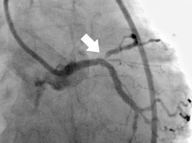
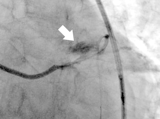
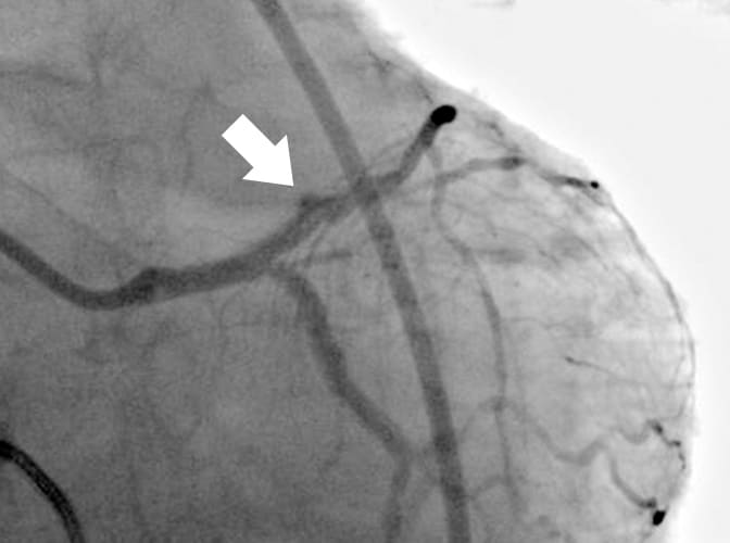
Fig. 2 Angiography can be performed even after the DCA catheter is inserted, and the catheter can be positioned easily due to good contrast
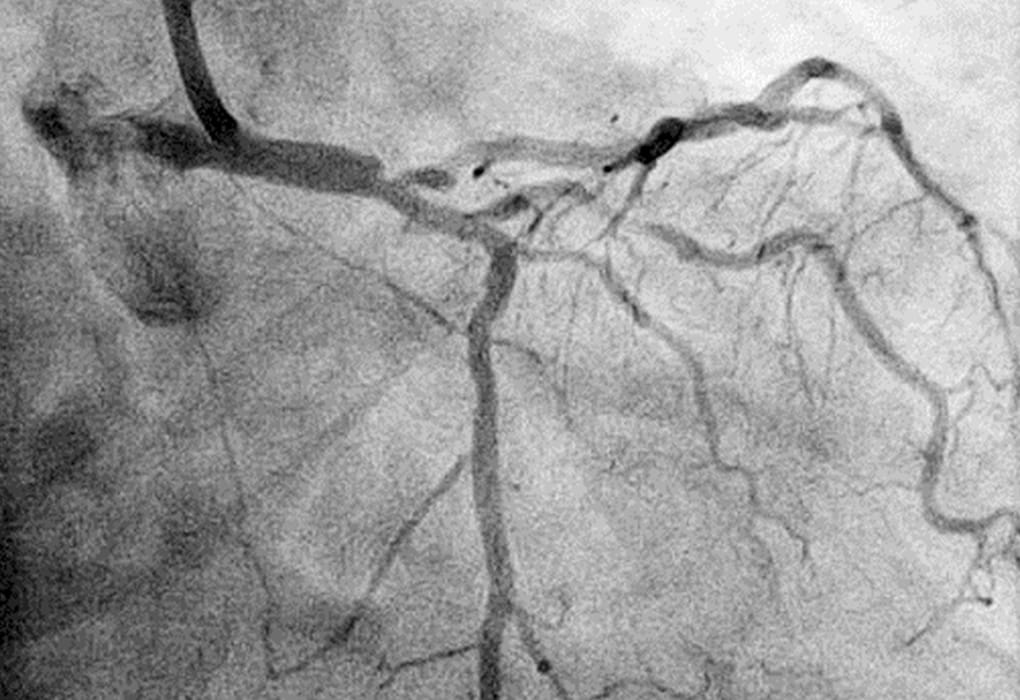
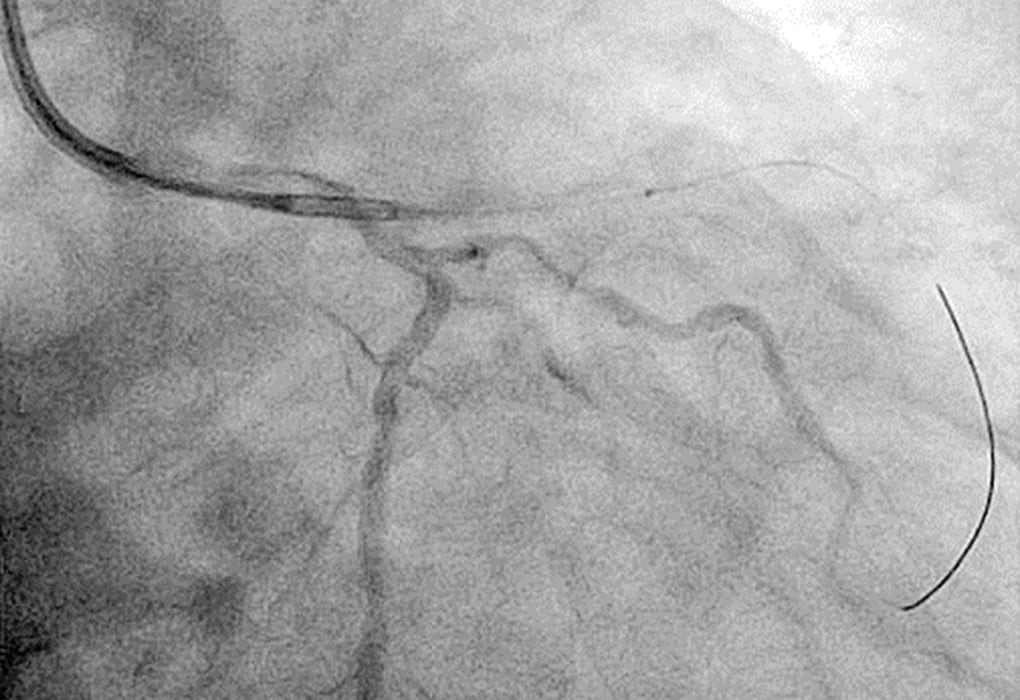
Fig. 3 In-Vitro Examination Using Copper Plate and Contrast Media: CNR Measurement
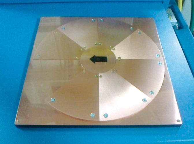
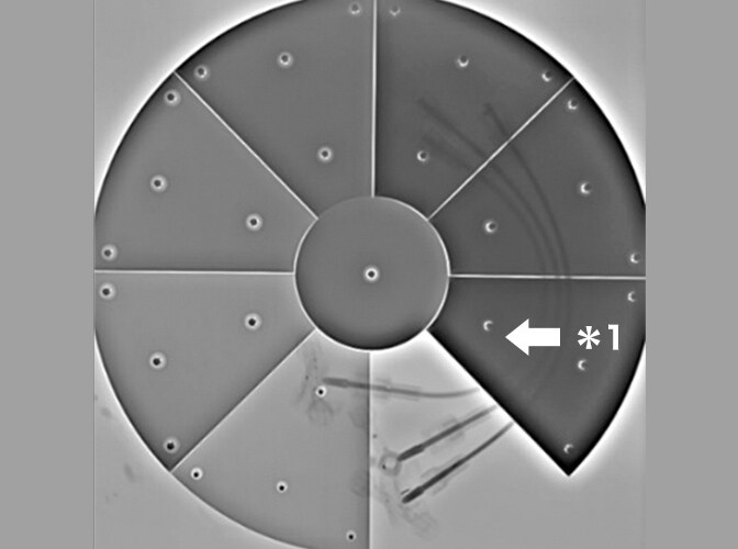
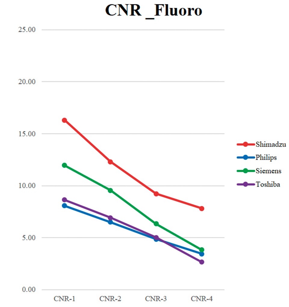
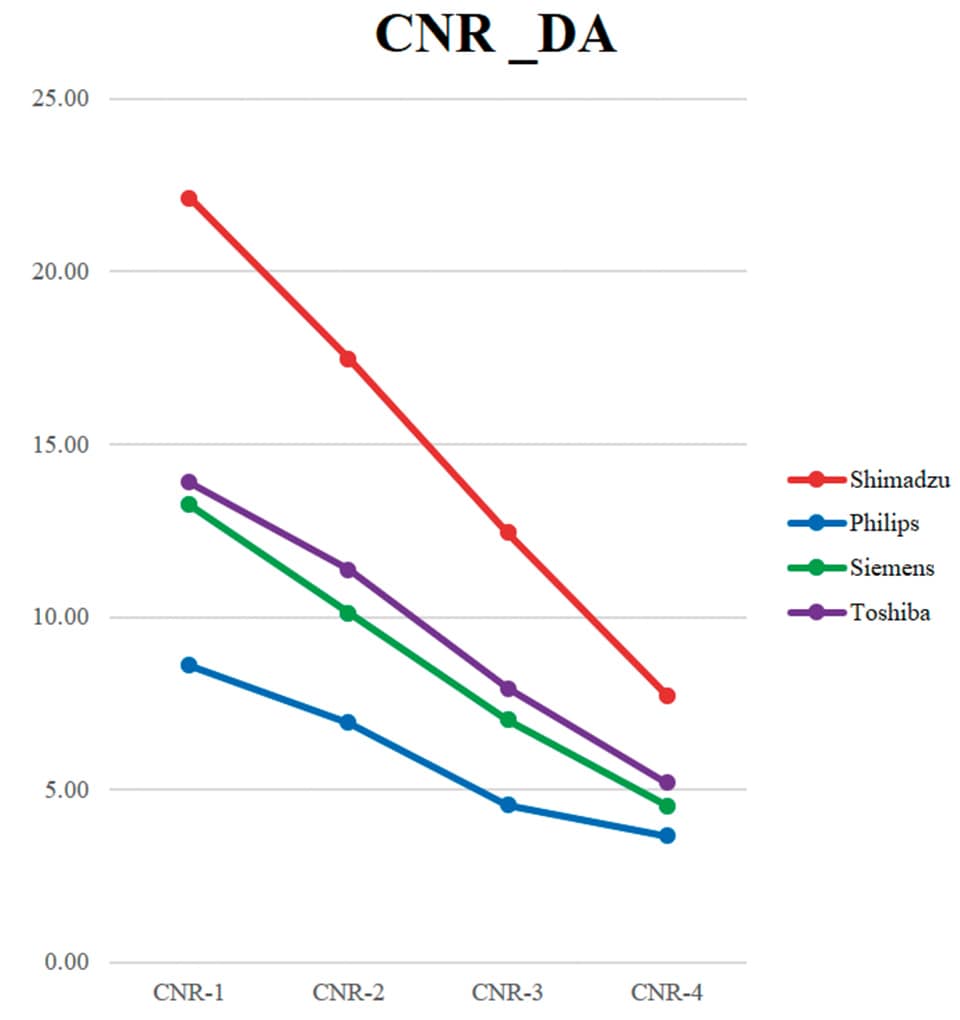
Software used: Xcat
4. Confirmation in the Transverse Direction
To eliminate errors in the transverse direction, it is important to (1) synchronize the IVUS and angiography images in your head and determine the direction of the target plaque identified in the IVUS image with respect to the angiography image, and (2) accurately rotate the DCA in the corresponding direction.
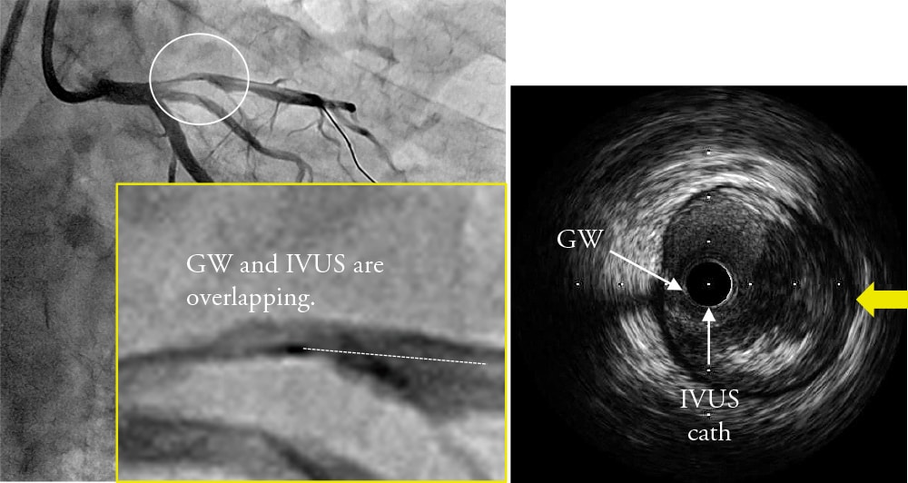
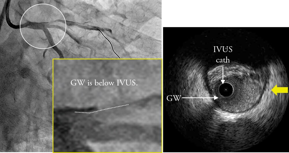
(1) Synchronizing IVUS and Angiography Images Synchronizing IVUS and angiography images normally requires confirming three things—1: the branch guide, 2: wire bias, and 3:
lumen bias.
Confirming the branch guide is important especially for DCA procedures between the main trunk and anterior descending branches.
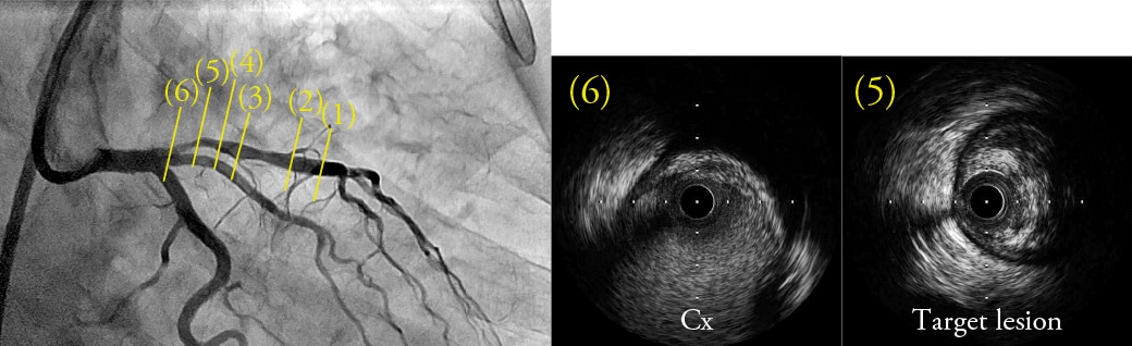
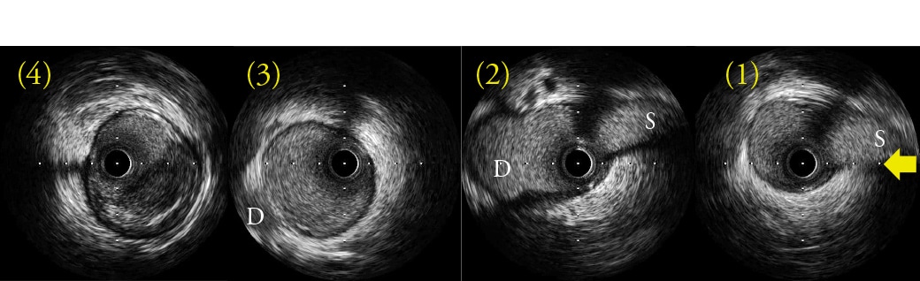
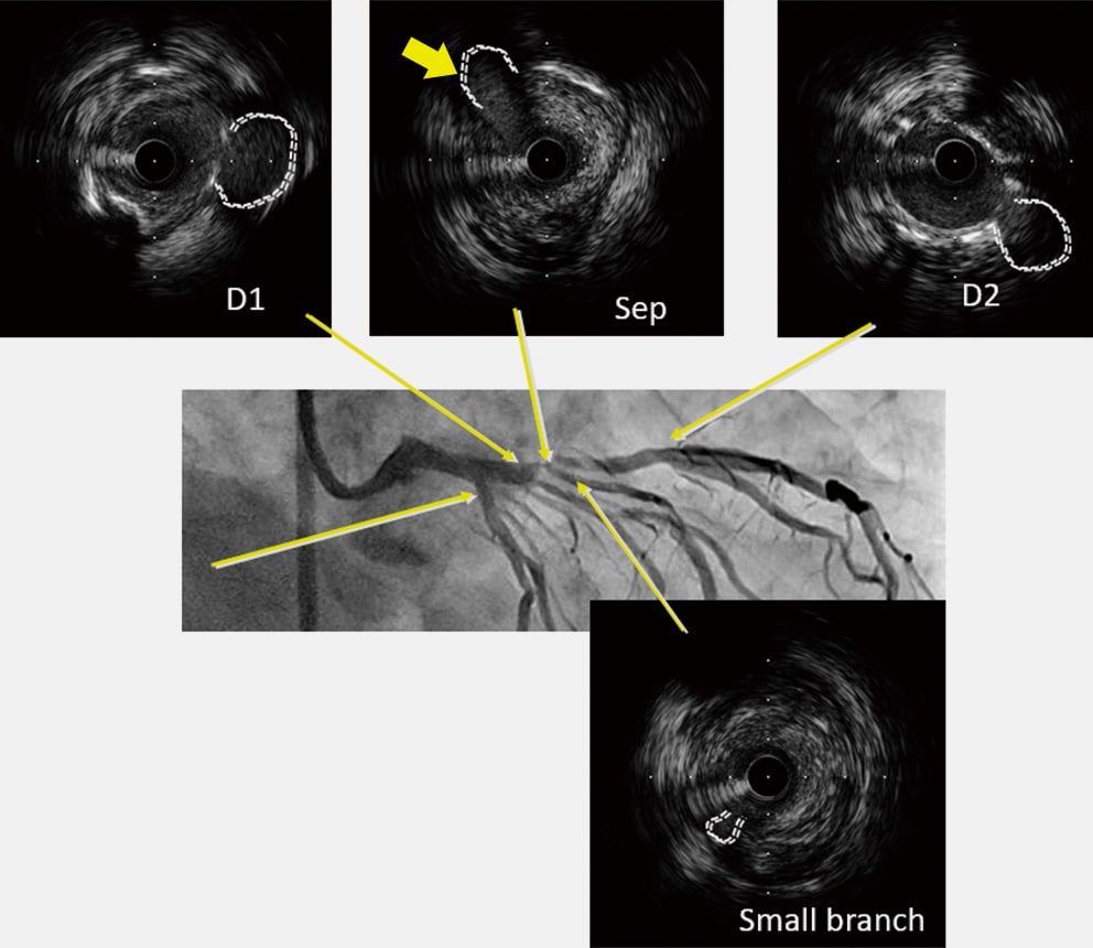
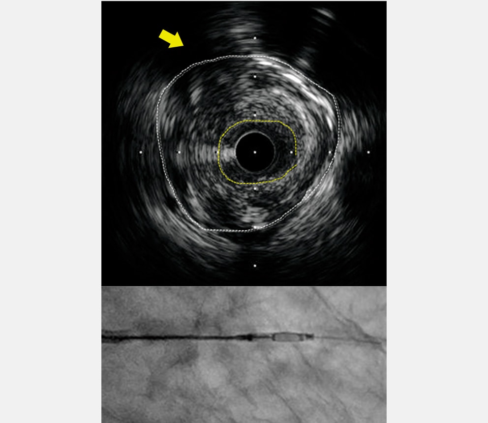
The diagonal branch generally bifurcates to the near side of the septal branch at the far side of the RAO caudal view, that fact can be used to synchronize the IVUS and angiography images. However, the appearance of branches can differ depending on the given case, even for circumflex branches, the right coronary artery, or the anterior descending branches, which can have many possible of visibility. Therefore, using the branch guide alone is not necessarily sufficient, so that the direction must be confirmed using the wire bias and lumen bias as well. Fig. 4 shows a lesion at the entrance to the anterior descending branch. In this case, the above three steps were fol lowed to di splay the R AO c auda l v iew f rom the three-o'clock direction of the IVUS image (yellow arrows). Since the target plaque is located in the three-o'clock direction (image (5) in Fig. 4) of the IVUS image, the DCA procedure is performed by orienting the cutter housing in the RAO caudal view toward the near side.
Normally, we use the above method to synchronize IVUS and angiography images, but in the future, we are very hopeful about using the branch guide in conjunction with Trinias's SCORE Navi+Plus functionality for coordinating images with the coronary CT system, which makes it extremely easy to determine the branch guide status.
An example is shown in Fig. 5. By downloading CT images acquired before procedure to the SCORE workstation outside the catheterization room, only a single click is required to display a window with four views that show a volume rendering (VR) image, axial image, coronal image, and sagittal image (image (2) in Fig. 5). By using those views to move images so that the LAD and septal images are aligned, it is easy to find the angle where the septal image is fully oriented toward the operator. In this example, the optimal angle was determined as 31 degrees RAO and 40 degrees caudal before procedure started. Even the C-arm could be operated by pressing a button to send the optimal angle. That should result in the septal branch appearing at the near side of the view, so that the branch guide can be used to easily synchronize it with the IVUS image (eleven-o'clock direction in IVUS image). Once the images are synchronized, the target plaque is confirmed in the IVUS image and the DCA catheter window is turned toward the target (image (5) in Fig. 5).
Fig. 4 Determining the Transverse Direction Using the Branch Guide, Wire Bias, and Lumen Bias
-
Branch Guide
-
Wire Bias
-
Lumen Bias
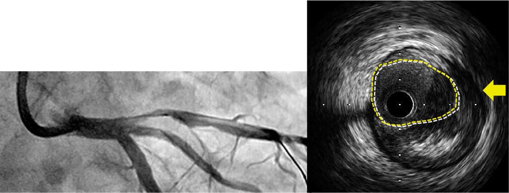
IVUS is below lumen. 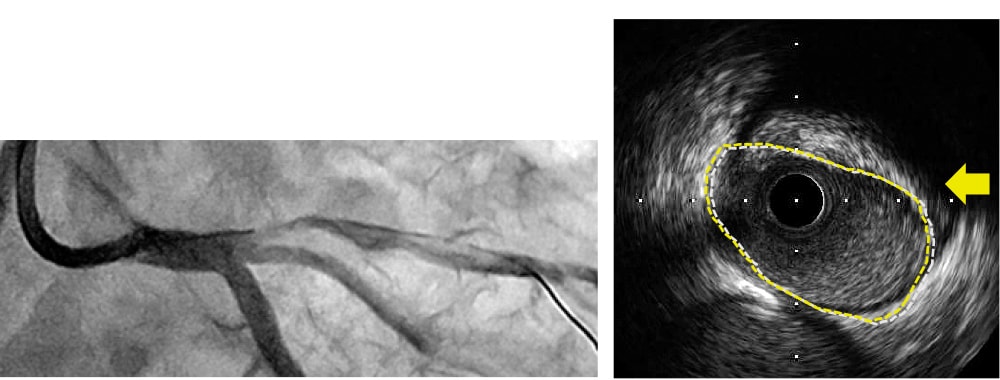
IVUS is above lumen.
Fig. 5 SCORE Navi+Plus with Linked Angiography and Coronary CT Systems
-
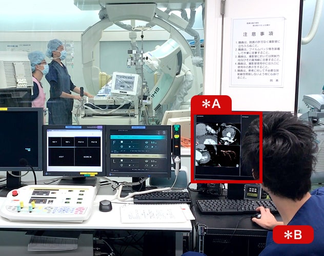
- 1. Trinias catheterization room at our hospital
- *A : SCORE 3D workstation
*B : Radiological technologist
-
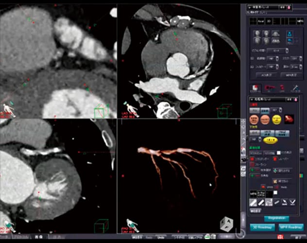
- 2. SCORE 3D workstation
- The coronary CT image is used to search for an angle where the diagonal or septal branch is completely horizontal.
-
- 3. Moving the C-arm
- Once the angle is determined at the workstation (in this case, the angle where the septal branch was completely at the near side of the view was 31 degrees RAO and 40 degrees caudal), the C-arm can be moved to that angle by clicking the button.
-
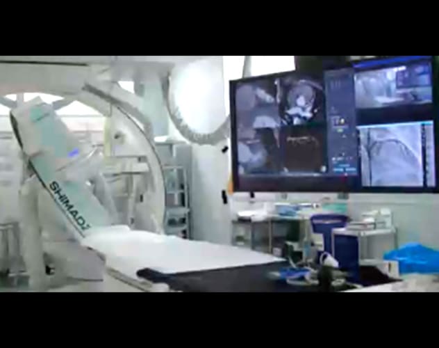
- 4. Using the branch guide to synchronize with the IVUS image
- Because the angle is set so that the septal branch is located at the near side of the view, it means the image is being viewed from the eleven- o'clock direction in the IVUS image.
-
- 5. Performing the DCA procedure
- Because the highest quantity of plaque was located in the eleven-o'clock direction of the IVUS image, the cutter housing was rotated toward the near side of the view to perform the DCA procedure.
(2) Determining the Orientation of the cutter housing of DCA Catheter.
Even if the IVUS and angiography images are synchronized as described above to determine the direction of the target plaque, all that work is meaningless unless the cutter housing of DCA Catheter can be actually rotated accurately to that orientation. Since the DCA catheter is controlled using fluoroscopy, the DCA catheter can sometimes move during balloon inflation, which can change the
orientation of cutter housing. A whipping motion can also occur when torque builds up while rotating the catheter and then is suddenly released, so that the catheter suddenly rotates energetically.
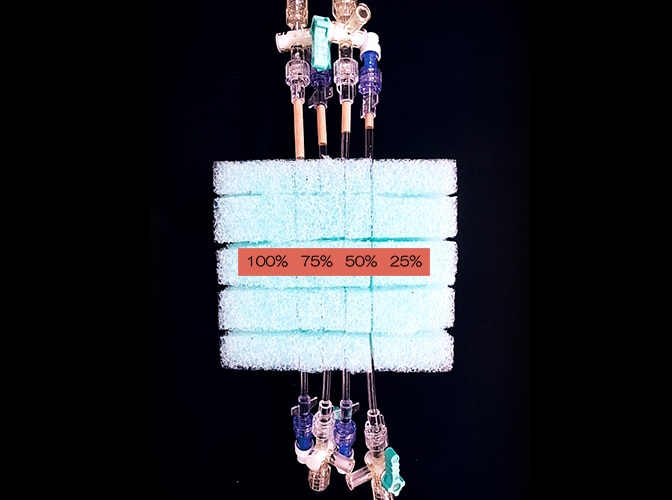
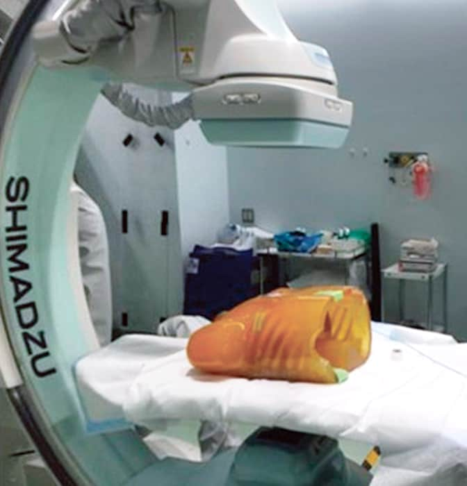
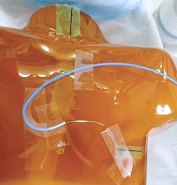
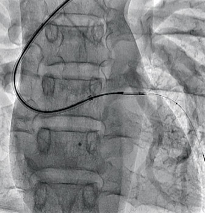
Consequently, angiography systems used for DCA procedures need to have imaging performance that enables the cutter movements and orientation of cutter housing to be determined accurately. Therefore, we performed an experiment similar to the in-vitro CNR measurement described above, by affixing a DCA catheter onto a chest phantom and then comparing how well the cutter movement and the orientation of cutter housing could be determined in the fluoroscopic images obtained using the four angiography systems at our hospital (Fig. 6). Though it involved subjectivity in evaluating the images, cutter movement was visible at 7.5 pps (pulses per second) of fluoroscopy on all four systems, but the Shimadzu system seemed to have the best contrast. Whipping motion could not be accurately confirmed at 7.5 pps on any of the systems, but housing rotation could be recognized to a certain extent when the frame rate was increased to 15 pps. Therefore, we recommend increasing the pulse rate to 15 pps for DCA procedures. In fluoroscopic images at 15 pps, the whipping motion and the orientation of cutter housing could be determined the most clearly using the Trinias system. That might be due to reduced image lag provided by the state-of-the-art motion tracking noise reduction image processing technology included in the Trinias system. However, we have also heard reports that the latest torque improvements in the ATHEROCUT® catheter have reduced the whipping motion enough to enable detailed angle adjustment, which makes us even more hopeful about the fluoroscopic imaging performance of the Trinias system.
Fig. 6 In-Vitro Test of Cutter Movement and Window Orientation
5. Summary
Several angiography system performance requirements for DCA procedures were indicated. Due to the higher contrast provided by the Shimadzu Trinias system, sharp angiographic images can be obtained, even for vessels during DCA catheter insertion. In addition, lower image lag levels make it easier to determine DCA catheter cutter movement and the orientation of cutter housing. That is a significant advantage for DCA catheterization procedures, compared to the other brands. The SCORE Navi+Plus functionality for linking the Trinias images seamlessly to coronary CT images currently seems a little incomplete and not fully perfected, but nevertheless provides information that is very useful for performing DCA procedures, and has the potential for developing into an essential device in the future.
Trinias Today (2017.6)