Gas Samples
■ Introduction
This page describes the measurement method for gas samples or easily vaporized samples. Such samples are generally measured by the transmission method using a gas cell. When making these measurements, several key points must be considered. Also, the appropriate gas cell for the application must be selected from among various gas cells. The page below describes the key points to consider when measuring gas samples and the measurement methods using different types of gas cell.
■ Key Points During Measurement
In a solid or liquid sample, the molecules are in an associated state. There is no major difference between their spectral resolutions measured at 0.5 cm-1 high resolution and at normal 4 cm-1 resolution, except at ultra-low temperatures. However, the spectral resolution of gas samples differs significantly according to the FTIR resolution. This is because in a gaseous state, many absorption peaks with a detailed structure appear due to the transition between rotational energy levels as well as the transition between energy levels caused by molecular vibrations. Therefore, high resolution is required to clarify the detailed structure inherent to a gas sample. Fig. 1 shows the infrared spectrum of 25 ppm NO gas measured at 0.5 cm-1 and 1 cm-1 resolution. The difference in resolution is apparent in the ranges 1945 to 1900 cm-1 and 1850 to 1795 cm-1.
Instrument functions called apodization functions are used in FTIR. Functions supplied include the box-car function, triangular function, and Happ-Genzel function. These functions each have their own characteristics. Select the box-car function for high-resolution measurements.
Water vapor has a strong effect during high-resolution measurements. Purging of the FTIR instrument is essential. If the sample contains moisture, it must be dewatered before it is introduced into the gas cell.
The cell internal pressure must be adjusted for quantitative analysis of the gas sample. Another factor that must be considered is the pressure broadening effect. Even if the gas sample partial pressures are the same, the absorption band width and absorbance coefficient may change according to differences in total pressure. Note also that the shape of the absorption band and the absorbance coefficient may change according to whether the coexisting gas has a small molecular radius, such as hydrogen, or a large molecular radius 1).
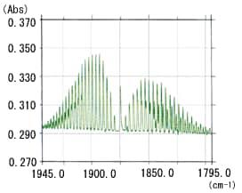
Fig. 1 Infrared Spectrum of 25 ppm NO Gas:(a) Resolution: 0.5 cm-1
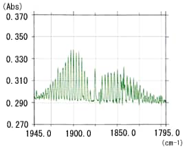
Fig. 1 Infrared Spectrum of 25 ppm NO Gas:(b) Resolution: 1 cm-1
■ 5 cm and 10 cm Gas Cells
Fig. 2 shows gas cells with a 5 cm and 10 cm light path. The cell body is a circular truncated cone made of glass. Each end is covered with a KBr or KRS-5 window that transmits infrared light. The internal volume is 42 mL for the 5 cm light path cell and 98 mL for the 10 cm light path cell. As the infrared light passes through the gas cell only once, the gas cell internal pressure is slightly increased when measuring low-concentration samples.
To introduce a gas sample into these gas cells, first connect one of the taps to a vacuum pump and open it to evacuate the cell. After closing the tap, connect the other tap to the sample and open it to fill the gas cell with the gas sample. Set the internal pressure from several tens of Torr to 760 Torr.
No pressure gauge is attached to these gas cells, so use a sampling system with a manometer, as shown in Fig. 3, to adjust the pressure when filling the cell. Connect the gas cell, manometer, and vessel containing the sample, as shown in Fig. 3. Open taps K1, K2, and K3 to evacuate the gas flow line, and close K3. Then, close K1 and gradually open K4 to allow the sample to flow into the gas cell. Watch the manometer and close K4 when the appropriate pressure is reached. Finally, close K2 and remove the cell to perform the measurements.
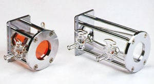
Fig. 2 Gas Cells with 5 cm and 10 cm Light Path
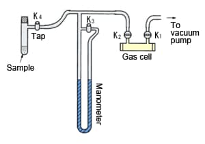
Fig. 3 Sampling System for Gas Samples
■ Long-Path Gas Cell
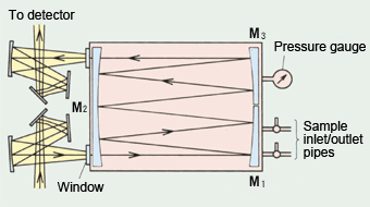
Fig. 4 Optics for Long-Path Gas Cell
A long-path gas cell with a light path of 10 m or 20 m is used to measure ppm-order or lower concentration gas samples. These gas cells do not offer a 10 m light path in a straight line. Rather, they comprise three mirrors, as shown in Fig. 4, and the long light path is achieved by repeated reflections within the gas cell 2).
The three mirrors shown in Fig. 4 have an identical radius of curvature and this provides the base light-path length of the gas cell. Infrared light from the light source is focused on the inlet port to the gas cell. It is then reflected from mirror M1 and focuses on mirror M2. The infrared light reflected from mirror M2 is reflected from mirror M3 and focused back onto mirror M2.
Fig. 5 shows the images formed on mirror M2. It comprises two levels. The 4n-2 and 4n (where n is a natural number) show the sequence numbers of the images formed on mirror M2. The infrared light reflected multiple times between mirrors M1, M2, and M3 is finally reflected from mirror M3 and is focused on the exit port before reaching the detector.
Fig. 6 shows the appearance of a gas cell. The long-path gas cell incorporates mirrors. Note that a gas cell with gold-plated mirrors must be used to measure corrosive samples. Normal aluminum mirrors deteriorate rapidly in such a gas.
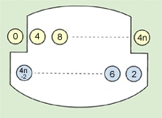
Fig. 5 Images on Mirror M2
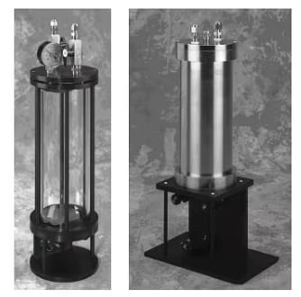
Fig. 6 The Appearance of a Gas Cell
■ Conclusions
Here we discussed the measurement methods for gas samples and their related key points. Although not described here, a wide range of gas cells is available. These include gas cells with a light path length of 100 m or more, heatable cells, and pressure-resistant cells. Select the appropriate type of gas cell for the application.
■ Reference
1) Shigeyuki Tanaka, "Sekigai-Raman Bunseki (Infrared and Raman Analysis)," Kyoritsu Shuppan Co., Ltd. (1978)
2) Infrared Analysis, Inc., Catalog 92