High-Sensitivity Reflection Method
Infrared spectroscopy incorporates diverse measurement methods, including the transmission method, diffuse reflectance method, and ATR method. However, a reflection method is required to measure substances adhered to or applied to a material that does not permit light transmission, such as a metal sheet.
Reflection measurements include infrared irradiation from an almost vertical angle of incidence to determine the reflectance of a material, and infrared irradiation from an almost horizontal angle of incidence to analyze thin sample layers (thin films) on a metal substrate, for example. The latter method is normally called the high-sensitivity reflection method or reflection absorption spectrometry (RAS).
(1) Principle of High-Sensitivity Reflection Method
The high-sensitivity reflection method is applied to samples adhered to or applied to a metal substrate, as shown in Fig. 1. Several percent of the incident light is reflected from the sample surface, while the 90 % or more residual light passes through the sample and reaches the substrate. As almost 100 % of the infrared light is reflected from the substrate, it passes through the sample again before measurement. As the infrared lights passes through the sample twice, the spectrum produced is almost the same as a transmission spectrum. For thin film samples, the absorption intensity is low during this double transmission, and becomes unsuitable for analysis.
The high-sensitivity reflection method is used to measure such thin films. Fig. 2 shows the optical system used in the high-sensitivity reflection method. Compared to Fig. 1, the angle of incidence is large, such that the transmission distance is longer through a sample of the same thickness. It is easy to see that the transmission distance has become longer. However, the sensitivity for the high-sensitivity reflection method increases by more than the amount of this effect. This increase in sensitivity is described below.
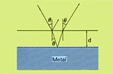
Fig. 1 Measurement of Sample on a Metal Sheet
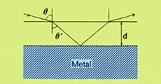
Fig. 2 Optics for High-Sensitivity Reflection Spectrometry
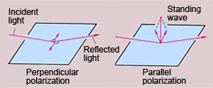
Fig. 3 Measurement by Polarized Light
Fig. 3 shows an example of a metal substrate irradiated by two types of linear polarized light. Perpendicular polarized light and parallel polarized light can be defined as follows. Assume that the incident plane is formed by a perpendicular line to the substrate and the incident line. Then, the light that oscillates within this plane is parallel polarized light, while the light that oscillates perpendicular to the plane is called perpendicular polarized light.
When infrared light hits metal and is reflected, a change occurs in the oscillation phase and a standing wave is generated at the metal surface. These standing waves are the same phenomena that occur in low-pressure wheels when driving at high speed. They can be thought of as "beats" in the infrared light at the metal surface. These beats are generated due to the phase difference between the incident light and reflected light. In perpendicular polarized light, these phase differences cancel each other out, such that the size of the standing wave ("beats") is almost zero. Therefore, this light is not useful for measuring thin films. With parallel polarized light, however, the phase changes are added in the upward direction and create a large standing wave ("beats"). This is absorbed by the thin film on the metal sheet and is useful for measurements. The magnitude of the standing wave can be increased by increasing the angle of incidence. Normally an angle of incidence between 75° and 85° is used, though it differs according to the type of metal substrate and the type of organic thin film. Since high-sensitivity measurement for thin films can be performed with the increased angle of incidence, this method is called "high-sensitivity reflection method." As only the parallel polarized light affects the absorption by the sample, using a polarizer for measurements increases the apparent peak size. Information on the sample orientation can also be acquired, as only functional groups with a perpendicular dipole moment with respect to the metal sheet are measured. However, such increases in sensitivity are available only with a metal substrate. Be aware that such high-sensitivity reflections do not occur from a glass or plastic substrate.
(2) High-Sensitivity Reflection Measurement Accessory
Fig. 4 shows the appearance of the RAS-8000 high-sensitivity reflection measurement accessory. Fig. 5 shows the optical system. It normally offers a mean angle of incidence of 70°, but 75° mean angle of incidence can be selected by attaching the light shielding plate. The sample is mounted by simply placing it facing downwards. Aluminum or a vapor-deposited mirror is normally used as the reference.
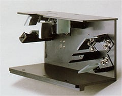
Fig. 4 Appearance of the RAS-8000
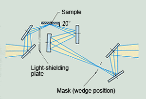
Fig. 5 RAS-8000 High-Sensitivity Reflection Measurement Accessory Optical System
(3) Examples of Measurements
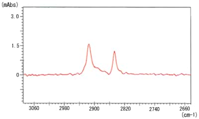
Fig. 6 High-Sensitivity Infrared Spectrum of Monomolecular Film on a Gold Mirror
Fig. 6 shows an example of a measurement by the high-sensitivity reflection method. The sample is a 25 Å-thick monomolecular stearic acid film formed on a gold mirror. The spectrum was measured at 80° angle of incidence with no polarizer. A clear infrared spectrum was obtained, even from such a extremely thin film.