3-4) Baseline Noise Caused by Bubbles Forming or Accumulating Inside Detector Cells
Problems with Formation of Bubbles in Flow Lines
If the column or detector cell is heated, bubbles can form more easily because the temperature of the solution passing through the cell is elevated and its pressure is close to atmospheric pressure. Furthermore, bubbles can form in a gradient system, even without heating. Section 2-3 described how the saturated solubility can decrease when solvents are mixed. For example, in the case of high-pressure gradient mixing, flow lines are kept under high pressure after mixing, which suppresses bubble formation, but bubbles can form in the cell, where the pressure is near atmospheric.
The formation or accumulation of bubbles in the detector cell can cause spikes and sawtooth noise or cause the baseline to fluctuate out of range. As a result, it prevents discriminating between peaks and noise, causes uncertainty about the baseline position, and prevents peaks from being integrated properly.
In the cases described in both 3-3) and 3-4), the pressure resistance of the cell is high (12 MPa and 3 MPa) if a UV or electric conductivity detector is used. Therefore, bubble formation can be prevented by applying back pressure to the detector outlet and increasing the pressure at the column outlet and inside the cell. Normally, back pressure is applied using a 2-m long stainless steel tube with 0.3-mm internal diameter connected as a flow restrictor. When water or methanol flows through this restrictor at 1 mL/min, it creates about 0.2 and 0.1 MPa of pressure, respectively. The reason the pressure differs for different types of solvents is due to solvent viscosity, which has an effect described by the following equation.
[Pressure] ∝ [Solvent Viscosity] [Flowrate] [Tube Length](provided laminar flow through a tube with constant internal diameter)
If used at preparative flowrates, the same restrictor tube would apply too much pressure. In this case, a shorter tube or one with a larger internal diameter (such as 0.8 mm, for example) must be used. On the other hand, for semi-micro LC or other low-flowrate applications (such as 0.1 mL/min, for example), the same restrictor tube would apply too little pressure. Therefore, this requires switching to a tube able to apply back pressure more easily, such as a 6-m long tube with 0.2-mm internal diameter.
Note: 1 MPa = 10.2 kgf/cm2 1 kgf/cm2 = 0.098 MPa
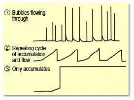
Fig. 14Baseline Noise Caused by Bubbles Forming or Accumulating Inside Cells
| Detector Type | Pressure Resistance MPa (kgfcm-2) |
| UV (VIS) Detector | Max. 12, (120) |
| Electric Conductivity Detector | Max. 3, (30) |
| Fluorescence Detector | Max. 0.5, (5) |
| Refractive Index Detector | Max. 0.4, (4)* |
| Electrochemical Detector | Max. 0** |
** When using an Ag/AgCl reference electrode
However, back pressure cannot be applied to electrochemical detectors, due to the low pressure resistance of the cell. In such cases, dissolved air must be degassed from the mobile phase in advance.
Based on problems due to bubble formation in flow lines, discussed above, the key factors are temperature increases, pressure decreases, and mixing solvents. Figure 15 shows an example of the relationship between flow lines, pressure, and temperature. Please use it to evaluate what area of your system is most likely to generate bubbles.
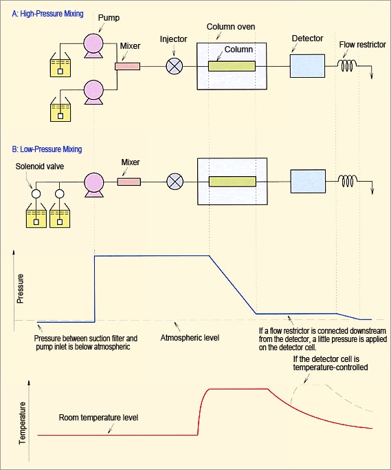
Fig. 15 Example of Relationship Between Flow Lines, Pressure, and Temperature
|
Note: |
This page is a partially revised html version of LCtalk Special Issue 5 (1991). |