What to Check When Solvent Delivery Pressure is Abnormally High
1. Introduction
We often receive calls asking whether the column needs to be replaced if the column pressure increases significantly. However, after inquiring about the problem, it often turns out that the solvent delivery unit was stuck at maximum pressure (press.max) and actually there was some other reason (such as clogging) besides the column. This page describes some of these other possible causes.
2. Background Knowledge
Potential Problems That Can Occur When Solvent Delivery Pressure Becomes Abnormally High
First, the following summarizes some of the problems that can occur if the pressure increases abnormally high.
A. If the column packing material is exposed to too much pressure, it can break apart or create flat spots, being pushed further into the column. This results in even higher pressure. If a gap opens in the packing material for the inlet, it can distort the peaks. In size exclusion chromatography, it reduces the pore size, which causes poor separation.
If the pressure is being applied downstream from the column and the pressure gradient of the column itself is low, the damage is relatively minimal.
B. Excessive pressure applied to the detection cell itself could cause leakage or cell breakage.
C. If tubing or filters become clogged with insoluble matter, liquid may not flow smoothly or component adsorption could cause peak distortion.
D. Excessive solvent delivery pressure can prevent delivery at the specified flowrates. It also can shorten the life of consumables.
Solvent Delivery Unit Maximum Pressure Setting (press.max)
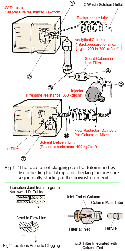
To identify problems as early as possible, set the [press.max] setting for the solvent delivery unit to between 1/2 and 2/3 of the column pressure capacity (for silica type 5 µm analytical columns, set it between 100 and 150 kgf/cm2). If there is a flow restrictor1) (see Figure 1), high sensitivity damper2), or pre-column3) installed between the solvent delivery unit and injector, pressure is applied to each of these, so the [press.max] setting value must be increased accordingly.
3. How to Check Flow Lines
First, Inspect the Mobile Phase Bottle
If there is any white cloudiness in the mobile phase bottle, it is as though insoluble matter is being packed into the flow lines. This is because even though a suction filter is provided, downstream filters often have a smaller pore size. Even if the mobile phase is filtered, barely dissolvable solutes can precipitate out when left idle. In fact, leaving merely pure water idle can cause bacteria to grow. Furthermore, before gradient elution of buffer solution and organic solvents, use a beaker or flask to confirm that no precipitation occurs after mixing. Even mixtures of organic solvents can become cloudy depending on the mixture ratio! If cloudiness or precipitation occurs, in addition to cleaning the flow lines, the mobile phase may need to be reconsidered.
In General, Disconnect Flow Lines Starting From the Downstream End
To find the location where pressure is increasing abnormally, in general, flow lines should be disconnected in sequence, starting from the downstream end, and solvent pumped through them to check the pressure. If the pressure reaches its maximum (press.max) right away, reduce the flowrate before checking. First, disconnect connection (1) in Figure 1 and pump the solvent (to check the backpressure tube4)). If the pressure drops off suddenly (by more than a few kgf/cm2), the backpressure tube is clogged. If there is no pressure drop, the blockage is further upstream, so disconnect and investigate connection (2) (to check the detector). Similarly, investigate the connections at (3) (analytical column), (4) (guard column and line filter), (5) (injector), (6) (flow restrictor, pre-column, etc.), (7) (solvent delivery unit line filter), and so on. Depending on the situation, disconnect other connections respectively as well. If the tubing, cells, filters, or injector experience more then several kgf/cm2 by themselves, there is a problem. Pay particular attention to areas that are prone to clogging, including filters and the inlet areas of narrow tubing.
Note that the flow lines in the column oven are checked with the oven open, which means it is nearly at room temperature. Therefore, pumping the same flowrate as during analysis could over pressurize the column. Normally, about half the usual flowrate is safe.
4. Corrective Measures for Different Areas
Flow line blockages include those that can be cleaned (dissolved) and those that cannot (Table 1). For blockages that cannot be cleaned, backflush or replace that portion of the lines.
Flow Line Tubing
Locations prone to clogging include transition joints from larger to narrower inner diameter tubing and bends in the flow lines (Figure 2).
Clogging can often be resolved by cutting off 1 cm from the inlet end of tubing. (In this case, it is convenient to use a hand-tightened PEEK male nut as a connector.)
Detector Cell
If the UV cell pressure is unusually high, disassemble the cell before cleaning to prevent breakage.
Columns
If column pressure is only somewhat high, perform a column check (measure the theoretical number of plates under the factory inspection conditions) to determine whether it satisfies usage objectives. If pressure is extremely high, the column should generally be replaced. Nevertheless, if the filter at the inlet end of the column is clogged, it might be resolved by the following procedure, though there is no guarantee.
(1) Backflush at about half the flowrate.
(2) Investigate the pressure at the inlet end of the column (assuming the filter is integrated with the column end, as shown in Figure 3). If that pressure is high, try cleaning it ultrasonically. If that does not improve it, replace the column end. However, if the new column end does not fit tightly to the ferrule (Figure 3), use thread sealing tape to prevent leakage. If the filter can be removed from the end, replace the filter.
If the inlet filter clogs frequently, insert a line filter between it and the injector. However, that will cause peaks to broaden slightly.
Line Filter and Injector
Either backflush or disassemble and clean ultrasonically.
| Blockage Substance | Cleaning (Dissolving) Solution | |
| Soluble | Low-Polarity Compounds | Organic solvents |
| Salts | Water, acidic water * , and basic water | |
| Metal fine powders | 0.1 N nitric acid | |
| Insoluble | Debris, dust, large metal particles | Since no cleaning solution is available, try backflushing |
* For example, 1 % aqueous acetic acid solution
Table 2 Examples of Combinations That Should Not Be Directly Mixed
| Examples of Solution Combinations | Problem | Measure to Avoid Problem |
| Water and Low-Polarity Solvent | Emulsion | Flush with 2-propanol or acetone |
| Buffer Solution and Organic Solvent | Precipitation | Flush with water |
| Nitric Acid and Alcohol | Reaction | Flush with water |
5. Situation Specific Measures
Usage After Extended Disuse
After an extended period of disuse or if the previous analytical conditions are unknown, rinse the flow lines without a column installed.
Extremely High Pressure Even During Delivery at Low Flowrates
If the pressure reaches its maximum (press.max) right away, even when the delivery flowrate is low, rather than disconnecting lines starting at the downstream end, disconnect all flow lines and connect each section directly to the solvent delivery unit, one at a time, starting at the upstream end.
Pressure Increases Each Time a Sample Is Injected
This is probably due to insoluble matter in the sample or to a soluble substance in the sample solvent that precipitates in the mobile phase.
Pressure Increases Slightly After Injection, but Then Falls
This is probably due to inadequate dissolution of sample components or to viscous resistance pressure increased when the sample solvent mixes with the mobile phase.
6. Points to Routinely Keep in Mind
Filter Mobile Phases and Sample Solutions
Be sure to always filter mobile phases and particularly sample solutions through a membrane filter. Furthermore, try mixing gradient solutions together and sample solutions with mobile phases to make sure there are no insoluble substances.
Make a Habit of Recording Pressures During Analyses
To discover any problems as soon as possible, routinely record pressure values occurring during analyses.
Adjust the Zero Point of the Solvent Delivery Unit
To ensure pressure can be monitored accurately, periodically adjust the zero point. Adjust the zero point with the drain valve open and nothing flowing.
Treating the Tip of the Detector Outlet Tube After Analyses Are Finished
The end of the outlet tube (backpressure tube) from the detector is exposed to air, so it tends to vaporize solvents inside the tube. After finishing analyses that use a buffer solution, insert the end of the tube into the waste liquid (replace it if turbid) or wrap it with Parafilm. If leaving the system unused for several days, disconnect the column and flush the LC lines with water, then with methanol. Of course, if a mobile phase that could shorten the life of the column was used, be sure to rinse it thoroughly before storage.
- Flow Restrictor: Here, a flow restrictor is a 2 m long flow line tube with an inner diameter of 0.1 mm, for example, that is connected to the outlet port of the solvent delivery unit to improve the efficiency of its high pressure damper, by increasing the load pressure at the analytical flowrate by several tens of kgf/cm2.
- High Sensitivity Damper: A damper used to obtain a baseline with high detection sensitivity in terms of electroconductivity, electrochemistry, and refractive index, by minimizing the pulse flow of delivery. Normally, it is used in combination with a flow restrictor.
- Pre-column: Installed upstream from the injector to protect the analytical column from mobile phases.
- Back Pressure Tube: A flow restrictor connected downstream from the detection cell (backpressure side). Typically a 2 meter long tube with an inner diameter of 0.3 mm is used for UV and other detectors. The pressure is about 2.1 kgf/cm2 for a water or methanol flowrate of 1 mL/min. It is used if air bubbles are generated when the cell is roughly at atmospheric pressure.