Monochromators
In this volume, we will describe the monochromator, an important part of the spectrophotometer that was explained in UV TALK LETTER Vol. 2 "The Structure of a Spectrophotometer".
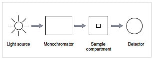
Fig.1 Construction of a Spectrophotometer
Light containing various wavelengths can be broken down according to the wavelength. White light (containing many wavelengths) entering the monochromator is extracted as green (540 nm), red (650 nm), or some other monochromatic (single-wavelength) light. The operating principle can be explained by an experiment using a prism to break down sunlight, as shown in Fig. 2. A slit can be inserted in the rainbow to extract monochromatic light. Fixing the slit and rotating the prism rotates the direction of the rainbow such that the color of the extracted monochromatic light changes.
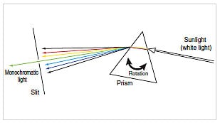
Fig.2 Prism Experiment
Breaking down light into its constituent wavelengths similar to a rainbow is known as "dispersion," and an element with this property is called a "dispersive element." The prism is a typical dispersive element. Another one is the diffraction grating. White light shining onto a diffraction grating reflects back in rainbow colors, as shown in Fig. 3. White light reflecting in rainbow colors from the surface of a CD is a result of the same dispersion phenomenon as the diffraction grating. In the same way as a prism, the diffraction grating can be rotated to change the color of the light extracted through the slit.
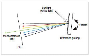
Fig.3 Using a Diffraction Grating
The monochromator comprises a dispersive element, an entrance slit and mirrors to create a parallel beam similar to sunlight, and an exit slit and mirrors to extract the monochromatic light.
1.Dispersive Element
The prism and diffraction grating are typical dispersive elements. Table 1 shows their respective features. Due to their superior dispersion properties, diffraction gratings are often used in modern spectrophotometers. The prism achieves dispersion due to the difference in the material refractive index according to the wavelength. However, the diffraction grating uses the difference in diffraction direction for each wavelength due to interference. The reflective blazed diffraction grating that is commonly used in spectrophotometers is described below.
| Prism | Reflective Diffraction Grating | |||
| Dispersion Principle | Exploits differences in the material refractive index according to the wavelength. | Exploits diffraction from a reflective surface with a regular grating structure. | ||
| Light Utilization Efficiency | High (Generally has high efficiency despite light losses from boundary reflection and absorption during transmission through the material. A single prism covers the range from 185 to 2500 nm.) | ✓ | Low (Light with the same wavelength is dispersed in several directions as higher-order light. High efficiency near the blaze wavelength.) | |
| Wavelength Dependency of Dispersion | Variable. High for UV;low for visible to NIR light. | High and approximately constant. | ✓ | |
| Temperature Dependency of Dispersion | High (Effects of temperature on refractive index.) | Low (Deformation due to temperature.) | ✓ | |
| Higher-Order Light | None | ✓ | Yes (Requires higher-order light cutout filter.) | |
| Stray Light | Low | ✓ | High (Dispersion due to higher-order light and surface roughness. Modern diffraction gratings achieve comparatively low stray light.) | |
| Polarization | Low | ✓ | High | |
Table 1 Comparison of Prism and Grating
(✓ : advantageous for spectrophotometer)
The diffraction gratings we study at high school are often a row of slits, as shown in Fig. 4. However, the reflective blazed diffraction grating has a sawtooth cross-section, as shown in Fig. 5. As light that passed through an adequately fine slit is diffracted, light reflected from an adequately fine sawtooth surface is also diffracted. There are 500 to 2000 serrations per millimeter.
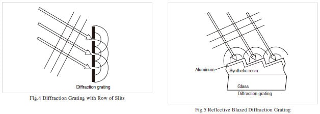
The sawtooth face of a commercially produced diffraction grating is the replica of a master grating. A thin synthetic-resin replica is stuck onto a glass sheet and coated with aluminum. The master was traditionally produced using a machine tool, but now the surface is formed by an ion beam or using laser beam photolithography. A smooth surface reduces stray light (light at unwanted wavelengths).
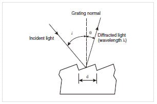
Fig.6 Basic Expression Governing Diffraction Gratings
This is the basic expression governing diffraction gratings: mλ=d (sin i + sinθ) ...(1) Where, d is the groove (serration) spacing, i is the angle of incidence, θ is the diffraction angle (positive if the incident light and diffracted light are on the same side of the normal to the diffraction grating surface, negative if they are on opposite sides of the normal), λ is the wavelength, and m is the order (see Fig. 6). This means that when d, m, and i are fixed, light of wavelength λ is diffracted in direction θ.
Expression (1) indicates the presence of higher-order light. If d, i, and λ are fixed in expression (1), a different value of m results in a different value of θ. This indicates that light of wavelength λ diffracts in multiple angles θ, as shown in Fig. 7. These light directions are named using a combination of the m value and the + or - sign, such as +1st-order light or -1st-order light. Incidentally, the light when m=0 is known as zero-order light, for which the diffraction angle θ is equal to the angle of incidence i. This is reflected as white light, equivalent to normal specular reflection.
The various light orders of a diffraction grating result in dispersion of the energy and a reduction in light utilization efficiency. However, the diffracted light energy from a diffraction grating with a fine sawtooth profile is concentrated in the direction of the specular reflection, as shown in Fig. 8. This wavelength is known as the "blaze wavelength." The diffraction grating in a spectrophotometer is normally used near the blaze wavelength.
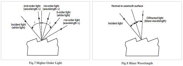
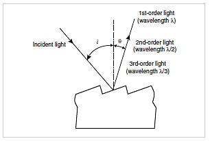
Fig.9 Higher-Order Light (2)
However, multiple diffraction gratings can be used separately to increase the efficiency over a wide range of wavelength. A different way of viewing the phenomenon of higher-order light is to say that, if d, i, and θ are fixed in expression (1), a different value of m results in a different λ. This indicates that light of multiple wavelengths θ diffracts in diffraction angles λ, as shown in Fig. 9. Therefore, a higher-order light cutout filter (short-wavelength cutout filter) is positioned after the monochromator exit slit to extract light at a specific wavelength (normally ±1st-order light).
2. Mountings (Aligning Elements)
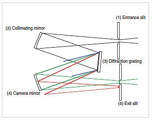
Fig.10 Basic Elements of a Monochromator (Czerny-Turner Grating Monochromator)
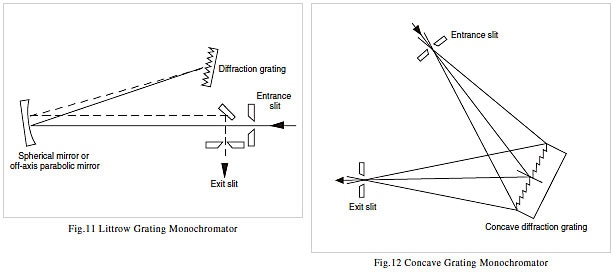
The basic elements of a monochromator are (1) entrance slit, (2) collimating mirror (to form a parallel beam after the slit), (3) diffraction grating (dispersive element), (4) camera mirror (focuses light from the dispersive element onto the exit slit), and (5) exit slit (see Fig. 10). In Fig. 2 and Fig. 3 a simple exit slit can extract the required wavelength, as the light beam incident on the dispersive element is narrow. A camera mirror is required in an actual monochromator, however, as light is incident over the entire surface of the dispersive element. This involves refocusing the image of the (1) entrance slit at the position of (5) exit slit at the wavelength to be extracted. The other wavelengths either miss (4) camera mirror or focus at some position away from (5) exit slit. Typical mountings used in spectrophotometers are the Littrow mount, Czerny-Turner mount, and concave mounts such as the Seya-Namioka mount. As shown in Fig. 11, the Littrow mount comprises a single spherical mirror or off-axis parabolic mirror that acts as the collimating mirror and camera mirror. The Czerny-Turner mount uses two symmetrically arranged spherical mirrors as the collimating mirror and camera mirror, as shown in Fig. 10. A concave mount uses a curved diffraction grating that offers both dispersion and focusing functions to simplify the construction, as shown in Fig. 12. This mount is used to reduce the number of mirrors where extreme resolution is not required.
3. Resolution
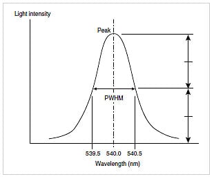
We described above how a monochromator acts to product monochromatic (single-wavelength) light from white light. However, while it is called single-wavelength light, it covers a certain range of wavelengths. For example, 540 nm light may extend from 539.5 to 540.5 nm. Consequently, when this light is used for measurements, information for the range from 539.5 to 540.5 nm is mixed together. This light is called "1 nmbandwidth light" and this monochromator is said to have 1 nm resolution. The smaller the wavelength band, the better the resolution. Fig. 13 shows how the resolution and bandwidth are defined as the peak width at half maximum (PWHM).
Once the monochromator elements and their positions are fixed, the resolution is determined by the slit width. As the light disperses as a rainbow, increasing the exit slit width reduces the resolution. A wider entrance slit results in a larger image at the exit slit position, such that the image for the wavelengths adjacent to the target wavelength enters the exit slit and reduces the resolution.
A diffraction grating has its own inherent resolution, which is determined by the diffraction principle according to the number of gratings. The improvement in monochromator resolution possible by reducing the slit width is limited due to this diffraction grating resolution, the aberration of the overall optical system, and mirror imperfections.
The monochromator slit width used in a spectrophotometer is expressed not as the slit width dimension but as the value of the resolution achieved. Setting the slit width to 1 nm, sets the monochromator resolution to 1 nm, such that 1 nm-bandwidth light shines onto the sample.
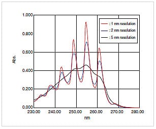
For measurements by spectrophotometer, the optimal resolution is determined by the spectral shape of the sample. A slightly larger slit width increases the light intensity reaching the detector and reduces the data noise but results in poorer resolution. Originally sharp spectral peaks broaden as shown in Fig. 14. A narrow slit width achieves a spectrum shape closer to the original spectrum. For example, if the original spectrum has a peak waveform, setting the slit width to between 1/8 and 1/10 the PWHM results in a measured peak with at least 99% the original height.1)
However, if the aim is not to determine the spectrum shape itself but to conduct concentration measurements using a calibration curve, these measurements are possible if the waveform is slightly imperfect. If noise detracts from measurement accuracy with the slit width set at 1/8 the PWHM, a slightly larger slit width may be appropriate. Shimadzu spectrophotometers normally achieve satisfactory resolution and light intensity for concentration measurements on solutions when the slit width is set between 1 nm and 2 nm. The slit width is normally set to 5 nm or above for measurements of solids using the integrating sphere. A larger slit width is set to reduce noise due to light losses in the integrating sphere, as high resolution is often not required when measuring solids.
4. Conclusions
We explained the monochromator, which extracts monochromatic light from polychromatic light. However, when monochromatic light enters the monochromator, it exits only in a direction specific to the diffraction grating. This property can be used to determine the wavelength of the monochromatic light.
This is the method normally used when the monochromator is used alone. A monochromator is incorporated into fluorescence spectrophotometers and emission spectrometers to determine the wavelength of fluorescence lines or emission lines emitted from the sample. In this case, the monochromator is located between the sample compartment and detector. The detector will be described in the next UV TALK LETTER. We hope you will continue to enjoy reading the UV TALK LETTERS.
In this volume, we will describe the monochromator, an important part of the spectrophotometer that was explained in UV TALK LETTER Vol. 2 "The Structure of a Spectrophotometer".