Solar Transmittance/Solar Reflectance Measurement
With global warming a major issue these days, lifestyles that place less impact on the environment are gaining in importance. For example, research to improve energy efficiency is being advanced in a variety of fields as typified by solar cells and hybrid cars. Measures for improving the efficiency of heating and cooling inside buildings are being devised. These include glazing and opaque film that allow visible light through but cut off the penetration of infrared light. Development is also is being conducted into roofing or paint for roofs that reflects infrared light. Measurement methods for evaluating the performance of these measures and calculation methods are stipulated in JIS standards, and are disclosed in JIS R3106 regarding flat glass, JIS A5759 regarding films for glazing used in construction, and JIS K5602 regarding paint films. The various measurement methods for flat glass conforming to JIS R3106 are introduced below.
JIS R3106 "Testing Method on Transmittance,Reflectance and Emittance of Flat Glasses and Evaluation of Solar Heat Gain Coefficient"
JIS R3106 stipulates methods for measuring and calculating visible transmittance, visible reflectance, solar transmittance, solar reflectance, and normal emittance as indices for expressing the properties of flat glass.
"Solar" in this context refers to the near ultraviolet, visible and near infrared wavelength region of 300 to 2500 nm that directly reaches Earth after penetrating the atmosphere. "Visible" refers to radiation of the wavelength range of 380 to 780 nm that is capable of passing through the visual sensory organs and causing visual sensation.
Visible Transmittance and Visible Reflectance
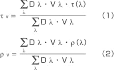
Visible transmittance (τv) and visible reflectance (ρv) refer to the ratio of the beam of visible light vertically incident on a glass surface to the incident beam of transmitted light or reflected light. These values are calculated by equations (1) and (2) below, using spectral transmittance (τ(λ)) and spectral reflectance (ρ(λ)), respectively, obtained by conducting transmittance measurement and reflectance measurement in the wavelength range of 380 to 780 nm using a UV-VIS spectrophotometer equipped with an integrating sphere. In the equations, Dλ·Vλ is the weight coefficient specified in JIS R3106 for calculating visible transmittance and visible reflectance.
Solar Transmittance and Solar Reflectance
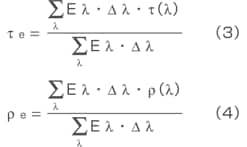
Solar transmittance (τe) and solar reflectance (ρe) refer to the ratio of the radiant flux of solar energy vertically incident on a glass surface to the transmitted radiant flux or reflected radiant flux. These values are calculated by equations (3) and (4) below, using spectral transmittance (τ(λ)) and spectral reflectance (ρ(λ)), respectively, obtained by conducting transmittance measurement and reflectance measurement in the wavelength range of 300 to 2500 nm using a UV-VIS-NIR spectrophotometer equipped with an integrating sphere. In the equations, Eλ·Δλ is the weight coefficient indicating the standard spectrum distribution of solar energy as specified in JIS R3106.
Normal Emittance (IR Measurement)
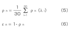
To determine normal emittance, specular reflectance (ρn(λ)) measurement is conducted in the infrared region 2000 to 400 cm-1 using an IR spectrophotometer equipped with a specular reflectance measurement attachment. Reflectance ρn is calculated from equation (5) using the reflectance of 30 specified wavelengths among the measured values. Then, normal emittance (εn) is obtained from equation (6).
Measurement of specular reflectance (ρn(λ)) is conducted in the range of at least 5 to 25 μm (wavenumber 2000 to 400 cm-1) at a resolution of 4 cm-1 or less within the ambient temperature's heat emittance wavelength region of 5 to 50 μm (wavenumber 2000 to 200 cm-1). If a certified surface-coated mirror is not available, the standard reflectance value specified in JIS R3106 is used. Also, if the measurement wavelength of 50 μm (200 cm-1) cannot be attained, the specular reflectance value at the measured upper limit wavelength is used as the value for longer wavelengths.
Measurement Example
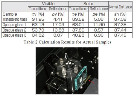
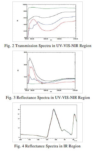
Measurements were conducted on four types of commercial plate glass to determine their respective visible transmittance, visible reflectance, solar transmittance, solar reflectance, and normal emittance values. Table 1 summarizes the measurement conditions that were used. Fig. 1 shows a glass sample placed on the integrating sphere. Figs. 2, 3 and 4 show the transmission spectra and reflection spectra in the UV-VIS-NIR region (correction by absolute reflectance of standard sample) and reflection spectra in the infrared region, respectively. The measured samples consisted of 1 type of transparent glass and three types of opaque glass (green: transparent glass, black: opaque glass 1, red: opaque glass 2, blue: opaque glass 3). It is clear from Figs. 2, 3 and 4 that large differences in both transmittance and reflectance exist in the UVVIS- NIR region, but the reflectance values in the infrared region were about the same. Table 2 shows the visible transmittance, visible reflectance, solar transmittance, solar reflectance, and normal emittance of each calculated sample. Calculation of the visible transmittance, visible reflectance, solar transmittance, and solar reflectance was conducted using the solar transmittance measurement software shown in Fig. 5 to easily obtain measurement results. Commercial spreadsheet software was used to calculate normal emittance.
| Visible | Solar | Normal Emittance | |||
| Transmittance | Reflectance | Transmittance | Reflectance | ||
| Analytical Instrument | UV-3600 UV-VIS-NIR Spectrophotometer ISR-3100 Integrating Sphere |
IRAffinity-1 FTIR Spectrophotometer SRM-8000 (Specular Reflectance Measurement Attachment) |
|||
| Measurement Wavelength Range | 380 to 780 nm | 300~2500nm | 5~25 μm | ||
| Resolution | 10 nm max. |
Less than 300 nm: 5 nm max.
380 to 780 nm: 10 nm max.
780 nm min.: 50 nm max.
|
4 cm-1max. | ||
| Incident Light Conditions | Close to parallel beam of light incident from the normal direction | Close to parallel beam of light incident from the radiation slit at an angle not exceeding 15° | Close to parallel beam of light incident from the normal direction | Close to parallel beam of light incident from the radiation slit at an angle not exceeding 15° Close to parallel bundle of rays incident from the normal direction |
Irradiation at an angle not exceeding 15° |
| Standard Sample for Comparison | The air layer is used as the standard sample, and its spectral transmittance is taken to be 1 | Specular reflector of reflectance specified by the absolute reflectance measurement method (sample 1), or specular reflector of reflectance specified by comparison with the sample 1 | The air layer is used as the standard sample, and its spectral transmittance is taken to be 1 | Specular reflector of reflectance specified by the absolute reflectance measurement method (sample 1), or specular reflector of reflectance specified by comparison with the sample 1 | Aluminum-coated mirror with certified absolute reflectance (float flat glass with vacuumdeposited aluminum film) |
Table 1 Measurement Conditions

Conclusion
Besides JIS R3106, which is related to flat glass, there are other solar measurement-related JIS standards: JIS A5759 regarding films for glazing used in construction and JIS K5602 regarding paint films. The explanation in this paper has dealt with JIS R3106. The next issue will deal with the other two standards. Though calculations based on JIS standards can also be performed by commercial spreadsheet software, calculation results can be obtained more easily by using dedicated software such as the Solar Transmittance Measurement Software shown in Fig. 5.