Xslicer SMX-6010 - Features
Microfocus X-Ray Inspection System
High-Accuracy Imaging
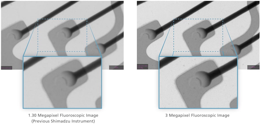
Equipped with a high-resolution Flat Panel Detector
Detailed internal structure and defects can be revealed due to the high-resolution flat panel detector (2.3 times larger than previously.
New HDR Processing Function
Shimadzu's unique, proprietary image processing technique/algorithm allows fluoroscopic images with a higher dynamic range, Regions that are both easy and difficult to penetrate can be observed at the same time, which shortens inspection times.

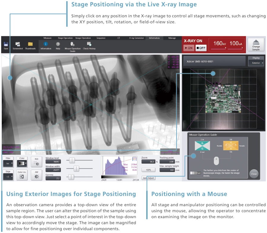
Simple Operation
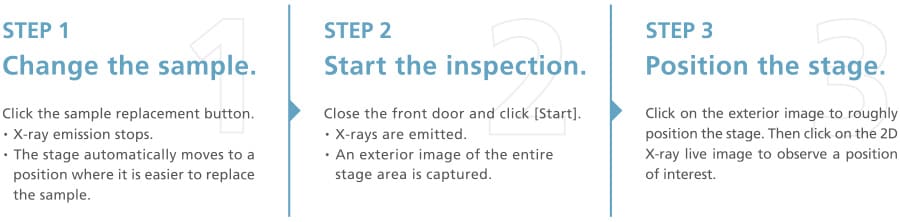
Imaging in Three Steps
Fluoroscopic imaging in just three steps.
A large monitor screen and simple button layout provide excellent visibility for intuitive operation.
X-ray inspections are easy to perform, even for operators using the system for the first time.
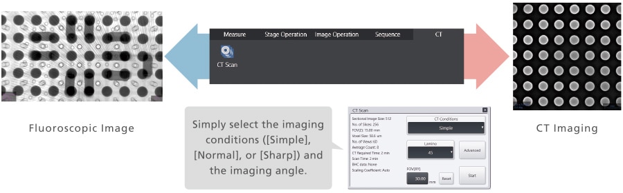
Switch Smoothly between Fluoroscopy and CT
Switch between fluoroscopy and CT imaging by simply clicking on the menu tab.
The Xslicer SMX-6010 features tilted CT imaging. X-ray fluoroscopic images are captured and cross-sectional images are created by tilting the flat panel detector and rotating it 360 degrees. There is no need to install a separate unit for CT imaging.
The CT imaging scan conditions are easy to configure just by selecting the scan mode, scan angle, and scan region.
A region of interest in the fluoroscopic image can be observed immediately with a CT scan.
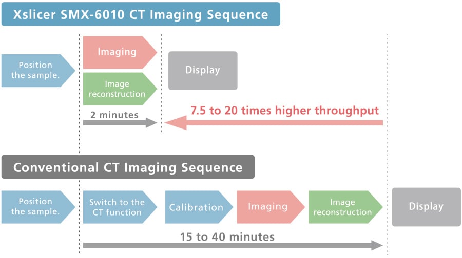
High-Speed Imaging and High-Speed Reconstruction
The calibration procedures are completely automated to speed up the imaging process.
Cross-sectional images can be displayed in as little as two minutes after CT imaging starts.
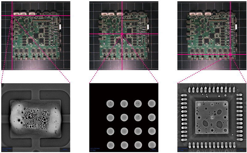
Wide PCT Imaging Range
PCT images can be obtained at any position within a 350 mm × 350 mm area (depending on the tracking point). There is no need to move the sample to the center of the rotary table as in conventional PCT, so the scan can be positioned just by clicking on the scanning site.
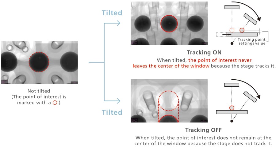
Set Tracking Points Easily
PCT images can be obtained at any position within a 350 mm × 350 mm area (depending on the tracking point). There is no need to move the sample to the center of the rotary table as in conventional PCT, so the scan can be positioned just by clicking on the scanning site.
Versatile, User-Friendly Functions
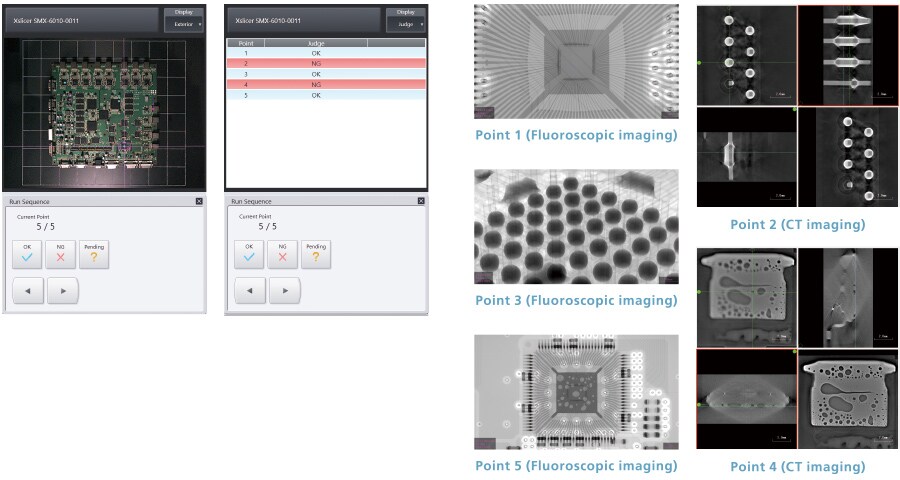
Teaching Function
Fluoroscopic and CT imaging can be automated using the Teaching Function, which moves the sample stage to preregistered points of interest.
Additionally, for visual inspection, OK and NG judgment functions are included.
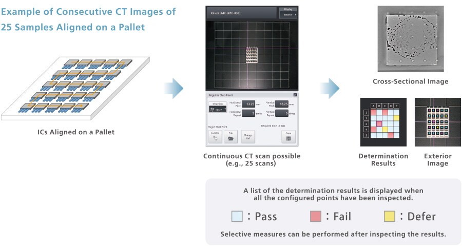
Stepwise Movement
The Stepwise Movement function moves the stage at constant intervals. It specifies the starting position, amount of movement, and number of movements. When this function is used, observations are performed while the stage makes consecutive movements from the starting position in accordance with the settings. Consecutive fluoroscopic or CT scans can be performed of samples arranged at set intervals.
Panoramic Imaging Function
A wide-range fluoroscopic image can be obtained just by specifying the imaging span on the external image. An improved stitching process ensures there are no visible lines in the panoramic image where the individual images are joined. A fluoroscopic image up to 32 megapixels in size can be obtained.
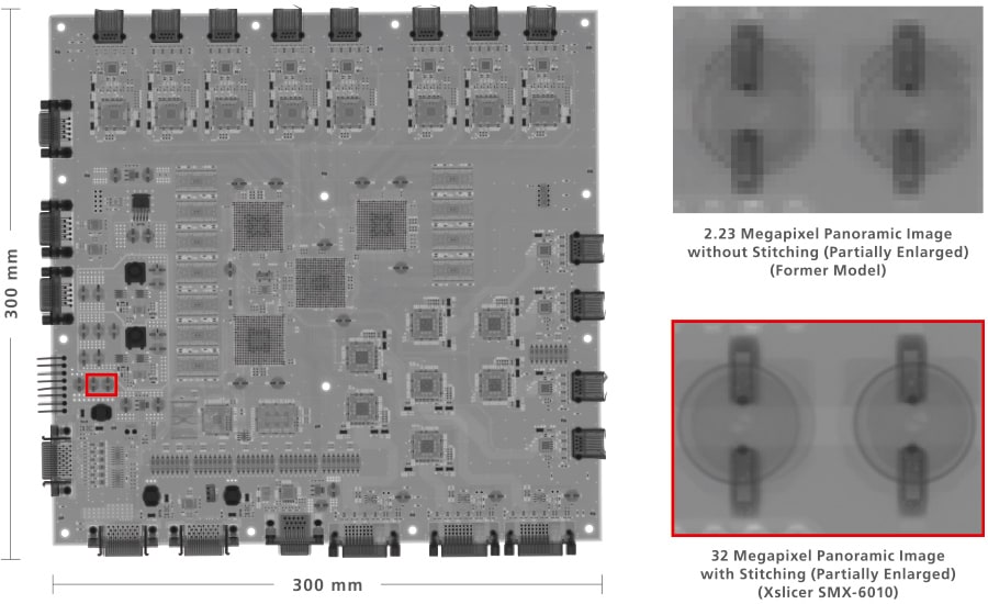
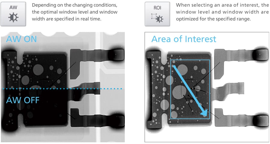
Image Adjustment Functions (Auto Window Function and Region of Interest Function)
The contrast can be automatically optimized to make the area of interest easy to see. Normally, with this sort of optimization function, the part outside the region of interest becomes difficult to see. However, a proprietary image processing algorithm automatically adjusts the image to ensure that the part outside the region of interest remains as easy to see as possible.
Ball Grid Array (BGA) Measurements
BGA bump diameters and void ratios can be measured.
With our proprietar y image proces sing algorithm, compl icated parameter set tings are unnecessary.*
Multiple settings can be saved and applicable ones can be accessed for each inspection target prior to measurement.
* Manual adjustments may be required depending on the sample.

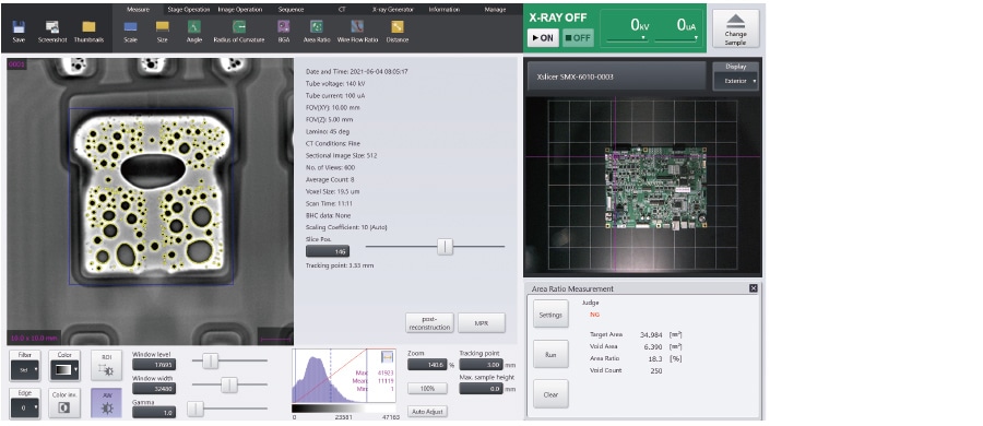
Area Ratio Measurements
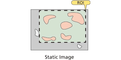
Die bonds, solder paste wettability, and other area ratios can be measured.
The parameter settings are not required thanks to Shimadzu's proprietary image processing algorithm.*
It is also possible to save multiple settings, and then call up the applicable settings for each inspection target prior to measurement. Furthermore, pass/fail determinations can be made based on the area ratio.
* Manual adjustments may be required depending on the sample.
* The measurement range (ROI) can be configured manually.
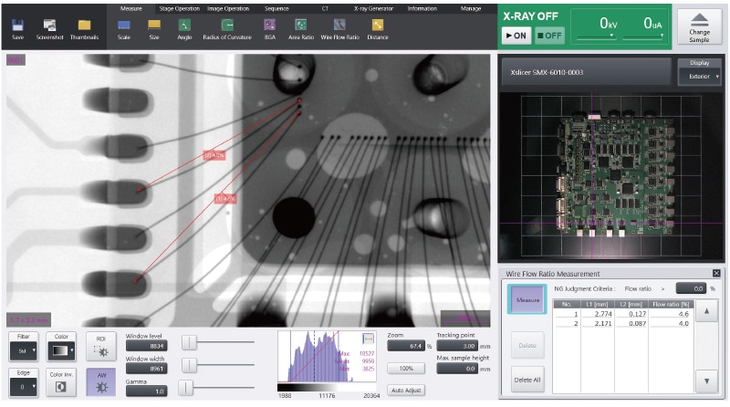
Wire Sweep Ratio Measurements
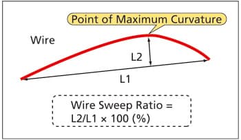
The wire sweep ratio can be measured by specifying both ends of the bonding wire and the point of maximum curvature.
Pass/fail determinations can be made depending on the wire sweep ratio.
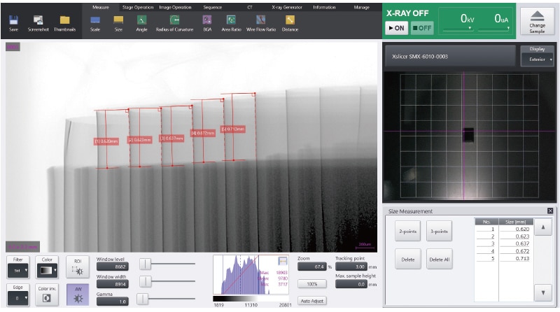
Dimension Measurements
The Xslicer SMX-6010 supports both 2-point distance and 3-point measurements.
With this system, sizes are measured efficiently by calculating calibration data internally in synchronization with the fluoroscopic magnification.