Multifaceted Evaluation of EV Hollow Shaft
To expand the use of electric vehicles (EVs), reducing the weight of vehicle bodies is necessary to increase the distance that they can travel. Reducing the weight of the shaft is particularly important because, in addition to improving the distance that can be traveled, this weight reduction is expected to improve the responsiveness of the motor by reducing the inertia. Here, a multifaceted evaluation of the material properties of a radial forging product, produced by a new forging technology, was performed.
Application News: Multifaceted Evaluation of EV Drive Motor Shaft Produced by Radial Forging
-
- Static tensile tests:
Tensile strength, Young’s modulus, and failure elongation were measured - Visualization of forging flow lines and element analysis:
Comparison of forging flow lines and distribution of Cr - Hardness tests and element mapping:
Measurement of Vickers hardness - Evaluation of the microstructure due to the forging process:
Measurement of the element distribution in small portions
- Static tensile tests:
-

1. Static tensile tests
Four types of test pieces were produced: three types cut from a radial forging product, and one cut from unforged material (blank product). The radial forging products were forged so that the reductions in cross-sectional area relative to the blank product were 50, 60, and 70 %.
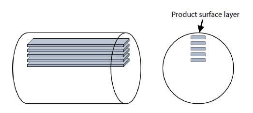
Image of Test Piece Sampling Positions
| Test Piece Material | SCr420 |
|---|---|
| Test Piece Dimensions | Thickness: 2.5 mm, width: 11 mm, length of the parallel portion: 56 mm |
| Types of Test Pieces |
Test piece (1) Blank product test piece |
| Test Piece Sampling Positions |
4, 10, 16, 22, and 28 mm |
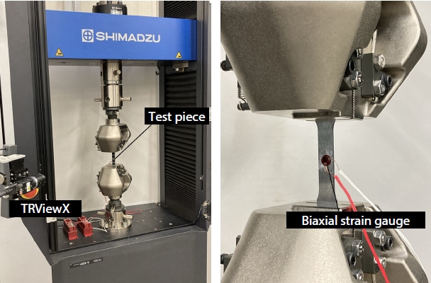
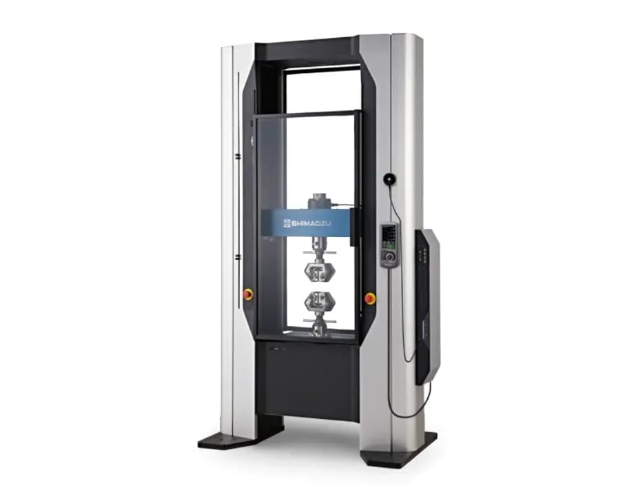
The TRViewX non-contact extensometer was installed to measure the failure elongation of the test piece. To accurately measure Young’s modulus and Poisson’s ratio, a biaxial strain gauge was fixed to the reverse side of the test pieces.
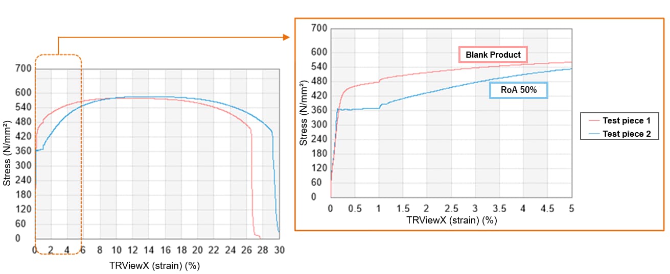
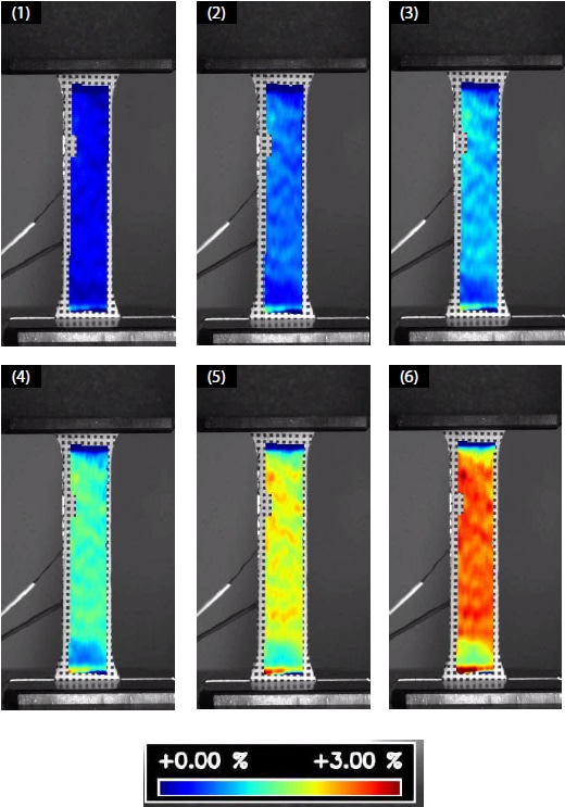
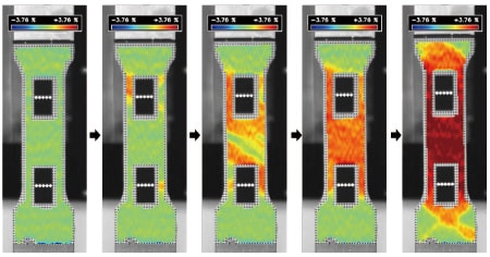
Strain Distribution of Radial Forging in Tensile Test (Left: Movie) (Right: Image)
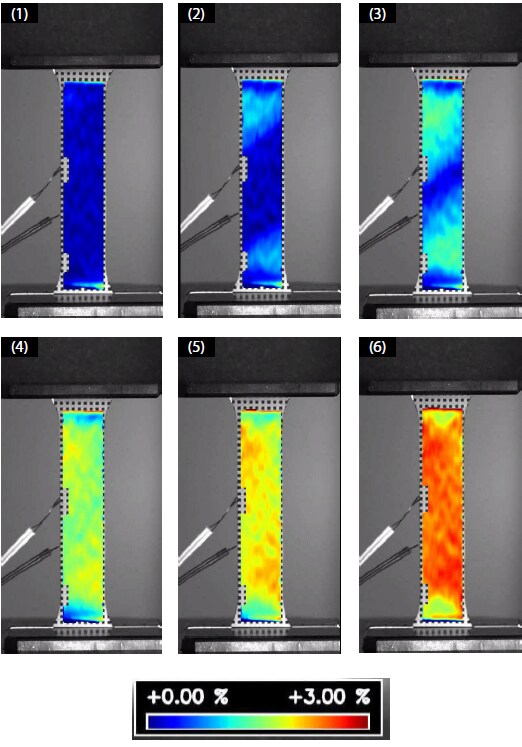
Strain Distribution of Blank in Tensile Test (Left: Movie) (Right: Image)
A yield point did not appear for test piece (1), the blank test piece, but for radial forging products, a yield point appeared as in test piece (2). In addition, there was a difference in the strain distribution between the blank product and the radial forging product.
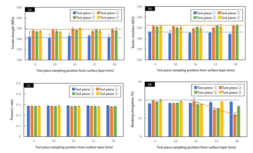
There were differences in the tensile strength and Young’s modulus between the blank product and the radial forging product, but there were almost no differences due to the position from which the test pieces were extracted. The value of Poisson’s ratio was virtually constant, regardless of the position from which the test piece was extracted or whether it was subjected to radial forging. The value of failure elongation was virtually constant up to 16 mm from the surface layer, regardless of whether radial forging was applied. On the other hand, for test pieces (2) and (3), the failure elongation was reduced at 22 and 28 mm. From these results, it was possible to determine the processed area where excellent properties were found.
Application and Related Product
2. Visualization of forging flow lines and element analysis
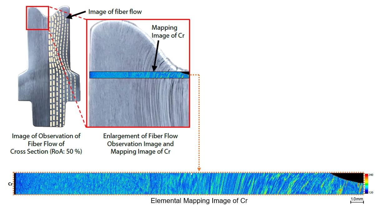
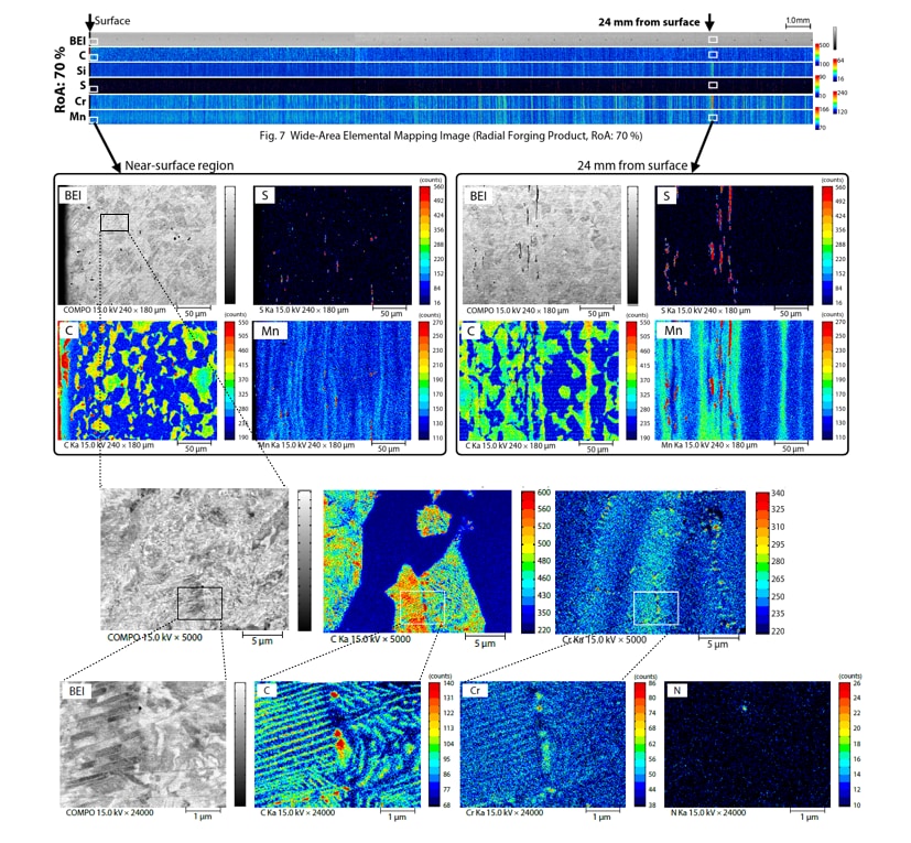
Superimposing the optical observation images of the forging flow lines, obtained by chemically treating the cross-section of the motor shaft that was forged by radial forging, and the EPMA element mapping images showed that the flow of the forging flow lines matched the element distribution of Cr very well. The forging flow lines that were refined by the forging operation were unclear when observed with an optical microscope, but it was possible to clearly observe them with the high resolution of EPMA.
Related Product

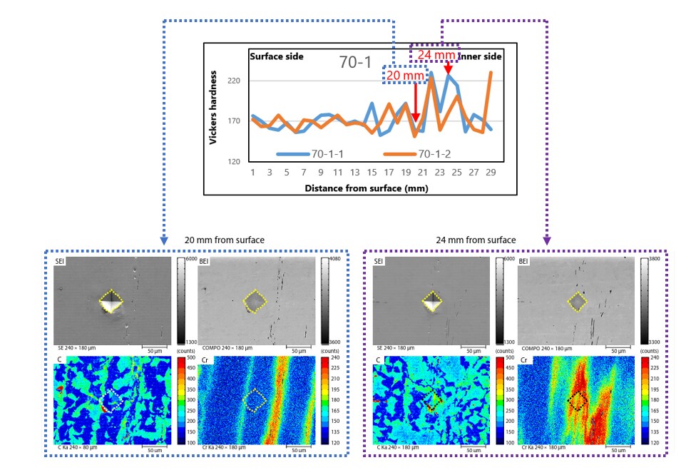
3. Hardness tests and element mapping

Test Piece Sampling Positions and Measurement Positions
Hardness measurements were taken on the radial forging product along the red dotted lines. The following table shows the hardness test measurement results. The greater the distance from the surface, the greater the variation in the results. Therefore, the points where the hardness measurements were large (24 mm from the surface) and small (20 mm from the surface) were enlarged and element mapping analysis was performed in the vicinity of these points. It was determined that a deviation in the distribution of C and Cr had affected the hardness.
Application and Related Product
4. Evaluation of the microstructure due to the forging process
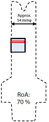
Test Piece Sampling Positions and Measurement Positions
Element mapping analysis was performed by EPMA within the red rectangle on the cross-section of the radial forging product. For Si, Cr, and Mn, a flow in a direction parallel to the surface was found, which matched the flow of the forging flow lines. Also, a more refined microstructure was found in the vicinity of the surface compared to the interior. Reflected electron images were obtained in which the crystal directions were reflected in the images, from which it was determined that a fine crystalline structure was formed by the forging process. When the C distribution was enlarged, a layered fine pearlite (microstructure in which ferrite (α-iron) and cementite (Fe3C) are separated) microstructure was formed. Looking at the distribution of Cr, it was found that grain boundaries had formed. In particular, the Cr high-concentration parts at the grain boundaries coincided with those of the C and N distributions, so it is considered that carbides and nitrides had formed. S had the same distribution as the parts where Mn had a high concentration, and it was found that MnS inclusions were formed. In addition, the shape and size tended to be different near the surface and in the interior. It is considered that changes were caused by the forging process and thermal changes.