MultiNA II MCE-301, Microchip Electrophoresis System for DNA/RNA Analysis - Support
Microchip Electrophoresis System
What Is Microchip Electrophoresis?
MultiNA II MCE-301, Microchip Electrophoresis System
Microchip electrophoresis uses a quartz substrate (microchip) with integrated channels and electrodes to separate DNA and RNA by nucleotide size. Compared to gel electrophoresis, the technique offers several advantages, including simplicity, automation, low cost, and high sensitivity. It is widely applied in a range of fields, primarily the life sciences, but also in pharmaceuticals, food analysis, and environmental analysis.
Principle of Microchip Electrophoresis
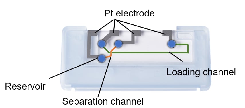
Within the microchip, a loading channel and a separation channel are arranged perpendicular to each other. Four reservoirs and platinum (Pt) electrodes for voltage application are located at the ends of the channels. Five reagent kits are available—four for DNA and one for RNA—and the appropriate kit is selected according to the type of analyte and the nucleotide size range. Each reagent kit* consists of two components: a separation buffer and a marker solution. Using the separation buffer as the medium, DNA and RNA in the sample are separated by size through a molecular sieving effect as they migrate through the channel. Before analysis, a fluorescent dye such as Gel Star or SYBR Gold is added to the separation buffer. The marker solution contains two reference standards—a low-molecular-weight marker and a high-molecular-weight marker—which serve as reference peaks for calculating the nucleotide size and concentration of sample components. The marker solution is mixed with the sample either before or during analysis. Electrophoresis is performed in the following three steps.
Microchip
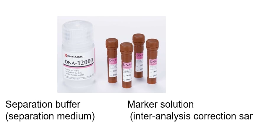
Reagent kit
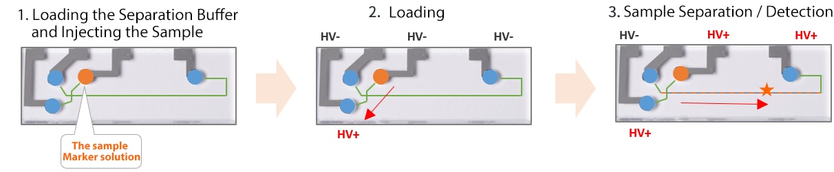
1. Loading the Separation Buffer and Injecting the Sample
A mixture of the separation buffer and fluorescent dye is loaded into the channel. The sample and marker solution are then injected into the reservoirs.
2. Loading
A voltage is applied to the electrodes of the loading channel, and the sample is introduced from the reservoir into the loading channel.
3. Sample Separation / Detection
A portion of the sample at the channel intersection is introduced into the separation channel and migrates toward the detection zone (★). As it travels through the separation channel, DNA/RNA binds to the fluorescent dye in the separation buffer and is separated according to nucleotide size. At the detection zone, the fluorescent signal generated by LED irradiation is detected.
Method for Calculating Nucleotide Size and Concentration
First, a size calibration curve is generated by running a reference sample (size standard). The sample is then run, and the nucleotide size and concentration of the unknown sample are calculated based on the calibration curve. A mixture of the marker solution and the size standard is analyzed.
1. Analysis of the Size Standard
A mixture of the marker solution and the size standard is analyzed.
2. Generation of the Size Calibration Curve
A size calibration curve is constructed from nucleotide size and migration time.
3. Analysis of the Sample
A mixture of the marker solution and the sample is analyzed. The nucleotide size of the unknown sample is estimated based on the size calibration curve. The concentration of each nucleotide size fraction in the unknown sample is then calculated based on the peak area values of the reference standards in the marker solution.
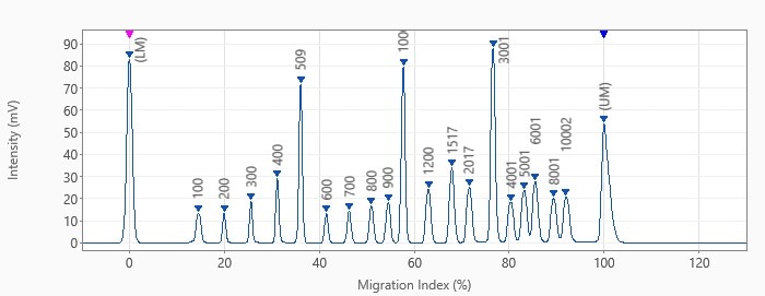
1. Electropherogram of Marker Solution and Size Standard
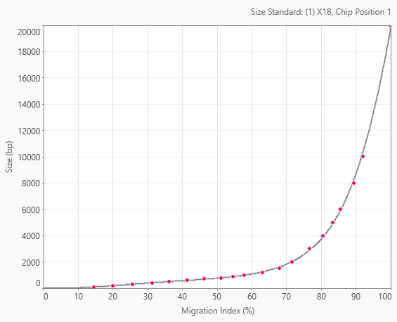
2. Size Calibration Curve